Potentiometer – Functions, Types and Applications
The Potentiometer. What is it? A potentiometer is a three-terminal resistor where resistance can be manually adjusted to control the current flow. Through today blog, you will learn:
- How does a Potentiometer work
- Types of Potentiometers
- Rheostat vs Potentiometer
- Logarithmic Potentiometer and Linear Potentiometer
- Applications of Potentiometer
How does a Potentiometer work?
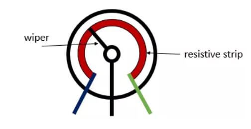
- Also known as a Potmeter or Pot, it consists of a resistive element called the track and a sliding contact called the wiper internally where end terminals are attached to the resistive element.
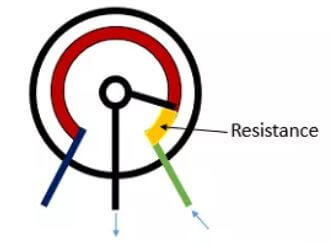
- Resistance is then adjusted with the manual wiper which is movable, touches a resistive strip of material. When it is moved up closer to terminal 1 and away from terminal 2, resistance is lowered to terminal 1 while resistance is raised at terminal 2 and vice versa.
- Input voltage will be applied across the resistor where output voltage will be the drop in voltage between the fixed and sliding contact as shown below.
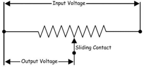
- They are used to accurately measure voltage and help achieve a variable voltage from a fixed-voltage source.
- They are passive devices which means they do not need power supply or additional circuits to function.
- Common Examples of Potentiometers are:
- Measuring Position on a gaming joystick
- Controlling audio equipment using volume controls
Types of Potentiometer
Currently, there are various Potentiometers out in the market. There are manually adjustable Potentiometers and there are also electronically controlled potentiometers. So without further ado, let us jump right in to the first type of Potentiometers.
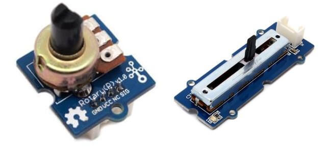
Rotary Potentiometers
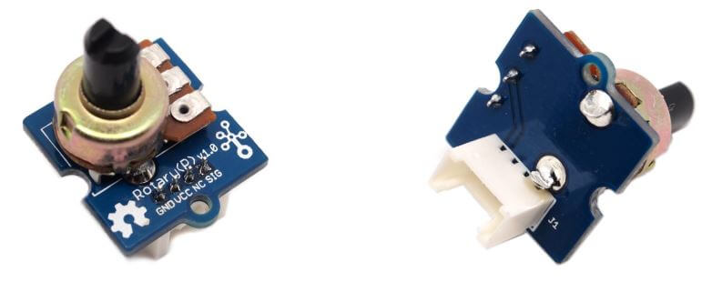
- These are the most common types of potentiometers currently where the adjustable wiper moves in an angular (circular) movement using a knob or dial.
- It is made up of 2 pins connected to a resistive element placed in a semi circular pattern and another connected to a rotary knob.and can produce a linear or logarithmic output with tolerances of 10% to 20%.
- In the rotary potentiometer family, there are various types:
| Type | How does it work? |
|---|---|
| Single – Turn Pot | Single rotation of approx. 270° or 3/4 of a full turn |
| Multi – Turn Pot | Multiple Rotation for increased precision |
| Dual – Gang Pot | 2 Potentiometers combined on the same shaft allowing parallel setting of 2 channels |
| Concentric Pot | 2 Potentiometers individually adjusted by concentric shafts which gives control of 2 Pots in one unit |
| Servo Pot | Motorized Pot which can be automatically adjusted by a Servo Motor |
- They are commonly used in audio equipment to adjust audio volume.
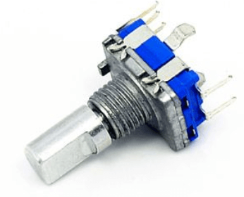
- Looking for a rotary potentiometer with a switch? We have them too:
Linear Potentiometers
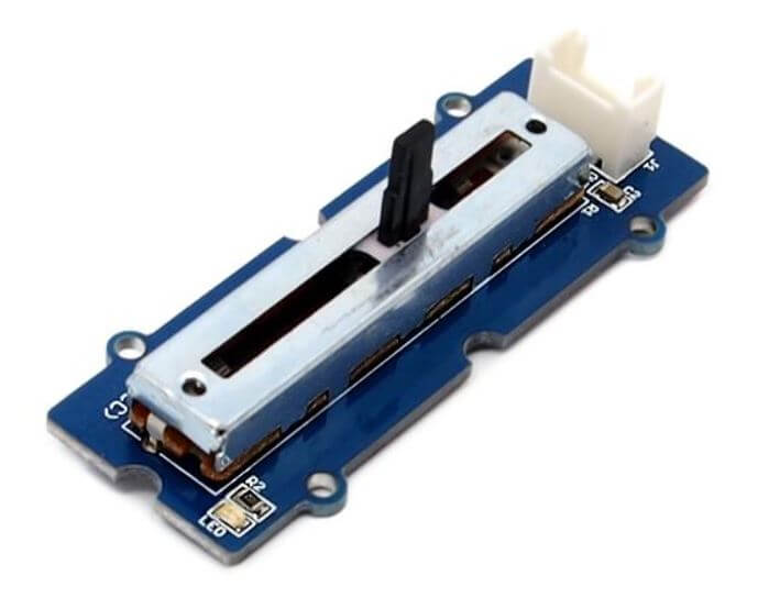
- Also known as the slider or fader, the linear potentiometers are similar to the Rotary Potentiometer but instead of the wiper moving in an angular movement, it moves linearly.
- It is made up of a pin connected to the adjustable slider where the other two pins are connected at both ends of the output circuit where the slider slides on the resistor through a track attached along the resistor.
- In the linear potentiometer family, there are various types:
| Type | How does it work? |
|---|---|
| Slide Pot | Single linear slider Potentiometer used for single channel control |
| Multi – Turn Slide | Made from a spindle which allow for multiple rotations for increased precision. |
| Dual-Slide Pot | Single slider controlling 2 potentiometers in parallel |
| Motorized Fader | Automatically adjusted fader using a servo motor |
- They are commonly used in audio equipment like audio mixers and graphic equalizers as they are easy to visualize from the position of the slider.
- However, some disadvantages of using a linear potentiometer is that
- Wiper can freely move up and down easily due to the long track
- Dust, dirt or sweat and grease may enter the open long track from the environment or the user.
Digital Potentiometer
- A digital potentiometer is a digitally-controlled electronic component that is similar to a potentiometer in terms of analog functions.
- They are 3 terminal devices where 2 pins are connected to end terminals and the last pin is connected to a wiper terminal to vary output voltage.
- Resistance between the end terminals can be adjusted through digital input signals like up or down signals or protocols using I2C and SPI.
- Even though using a digital potentiometer is far more complex compared to a rotary or linear potentiometer, they are still widely used in factory equipment due to their high accuracy as mechanical potentiometers are unsuitable due to its size, contamination of wiper track, mechanical wear, etc.
- Digital Potentiometers are also popular compared to mechanical potentiometers due to its:
- Small size – Multiple potentiometers can be packed together
- No moving Part
- Unaffected by environmental conditions (eg. Humidity, Vibrations, Shocks)
- Tolerance of up to ±1%
- Reliable
Rheostat
- The Rheostat is another function of the potentiometer which can be wired.
- The rheostat is a variable resistor which is used to control current with a 2 connections.
- Rheostats are commonly used for tuning and calibration in circuits.
So what are the differences between the Rheostat and the Potentiometer?
Rheostat vs Potentiometer
Potentiometer
- Uses all 3 pins of the Potentiometer
- 2 Pins are connected to a resistive element
- 3rd Pin connect to an adjustable wiper
- Used to give Variable Voltage = Control voltage by moving adjustable wiper on resistance.
Rheostat
- Can be configured by using only 2 pin out of the 3
- 1 pin connected to adjustable wiper
- 2nd Pin connected to a resistive element
- Give Variable Resistance = Control current by changing resistance with adjustable wiper.
Logarithmic Potentiometer and Linear Potentiometer
Potentiometers are associated with a concept called the Taper which is the relationship between the position and the resistance of the potentiometer. They are further differentiated according to their track which are:
Logarithmic Potentiometer
- They are normally indicated with a “A” on them.
- Eg. If they have a 10k resistance, they will be indicated with “A10K”
- Their resistance varies logarithmically and are non-proportional types of potentiometers.
- The change in resistance is much less at one end of the track compared to the other.
- They are used widely as volume controls in audio equipment as the human ear response to sound and loudness is also logarithmic.
- Due to their features, they are normally more costly then other types of Potentiometer.
Linear Potentiometer
- They are normally indicicated with a “B” on them
- Eg. If they have a 5k resistance, they will be indicated with “B5K”
- The resistance between one end of the track and the wiper varies linearly (constant rate) when the adjustable wiper is moved along the track.
- eg. Adjustable wiper moves by 20% = resistances is 20% maximum or minimum.
- The device depends on the electrical feature and not the resistive feature.
Applications of Potentiometers
Due to its characteristics and features, there are many different uses for a potentiometer. Some of them are:
Voltage Divider
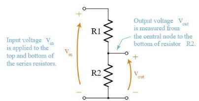
- A voltage divider is a passive linear circuit that produces output voltage that is a fraction of its input voltage.
- It scales down input voltage to a smaller voltage based on the ratio of the 2 resistors through distributing input voltage among components of the divider and are often used to supply a voltage different from an available battery or power supply.
- With a potentiometer, you can use it to obtain an adjustable output voltage from a fixed input voltage applied across the 2 ends of the potentiometer.
Interested? You can check out my other blog on the Voltage Divider here!
Arduino Potentiometer
- As the Arduino can read analog values, this means we can use it together with the potentiometer!
- Here is a short tutorial on how the potentiometer can be used with the Arduino in 4 steps!
What do you need
Step by step instructions
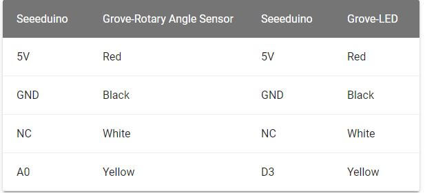
- Step 1: Connect Grove-Rotary Angle Sensor to A0 port and Grove- Green LED to D3 port of Grove-Base Shield
- If you do not have a Base shield, you can connect directly to Seeeduino as shown below with the Grove-LED connected to the PWM port. For Seeeduino, they are D3, 5, 6, 9, 10, 11.
- Step 2: Plug Grove-Base shield into Seeeduino (skip if you do not have Base shield)
- Step 3: Connect the Seeeduino to a PC via a USB cable. So far, your connection should look something like this:
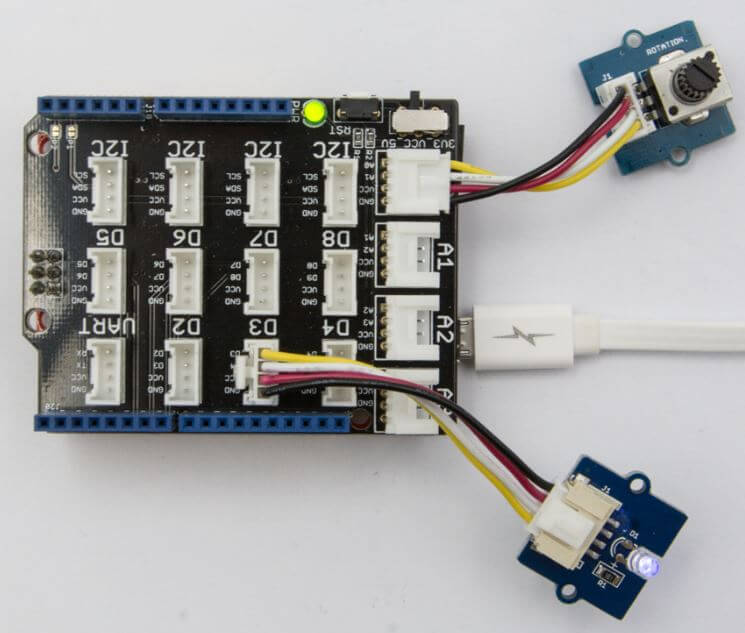
- Step 4: Copy the code below to Arduino IDE and upload to the Arduino. If unsure on how to upload the code, click here to find out how to upload code to your Arduino.
/*macro definitions of Rotary angle sensor and LED pin*/

#define ROTARY_ANGLE_SENSOR A0
#define LED 3  //the Grove - LED is connected to PWM pin D3 of Arduino
#define ADC_REF 5 //reference voltage of ADC is 5v.If the Vcc switch on the seeeduino
                    //board switches to 3V3, the ADC_REF should be 3.3
#define GROVE_VCC 5 //VCC of the grove interface is normally 5v
#define FULL_ANGLE 300 //full value of the rotary angle is 300 degrees

void setup()
{
    Serial.begin(9600);
    pinMode(ROTARY_ANGLE_SENSOR, INPUT);
    pinMode(LED,OUTPUT);
}

void loop()
{
    float voltage;
    int sensor_value = analogRead(ROTARY_ANGLE_SENSOR);
    voltage = (float)sensor_value*ADC_REF/1023;
    float degrees = (voltage*FULL_ANGLE)/GROVE_VCC;
    Serial.println("The angle between the mark and the starting position:");
    Serial.println(degrees);

    int brightness;
    brightness = map(degrees, 0, FULL_ANGLE, 0, 255);
    analogWrite(LED,brightness);
    delay(500);
}
And you are done! You can now adjust and play around with the Grove-Rotary Angle sensor and see the Grove- Green LED change in brightness.
Raspberry Pi Potentiometer
- Potentiometers can also work with the Raspberry Pi! Here’s how:
What do you need
Step by step instructions
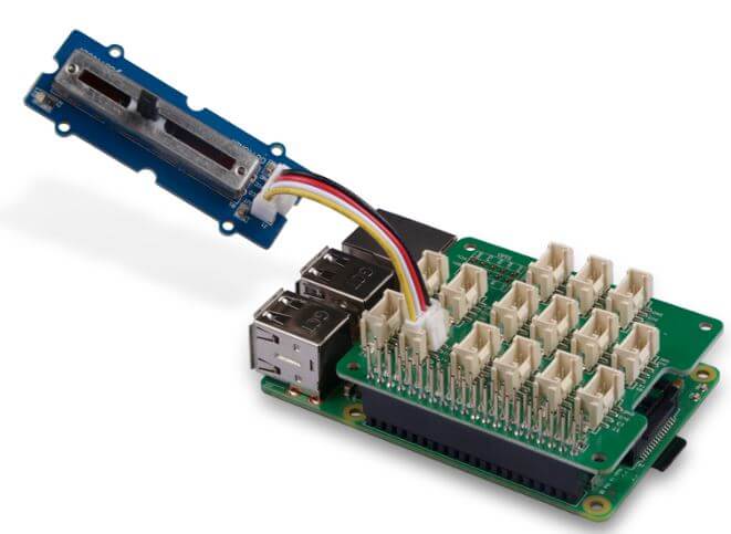
- Step 1: Plug Grove Base Hat into the Raspberry Pi 4
- Step 2: Connect Grove – Slide Potentiometer to A0 port of the Base Hat. So far, your setup should look something like this:
- Step 3: Connect the Raspberry Pi 4 to a PC using a USB cable.
- Step 4: Follow setting up of software here to configure the development environment
- Step 5: Download source file by cloning the Grove.py library by entering this code:
cd ~
git clone https://github.com/Seeed-Studio/grove.py- Step 6: Execute commands to run the code by keying in:
cd grove.py/grove
python grove_slide_potentiometer.py 0
The following will be Grove_Slide_Potentiometer.PY code
import math
import sys
import time
from grove.adc import ADC


class GroveSlidePotentiometer(ADC):
    def __init__(self, channel):
        self.channel = channel
        self.adc = ADC()

    @property
    def value(self):
        return self.adc.read(self.channel)


Grove = GroveSlidePotentiometer


def main():
    if len(sys.argv) < 2:
        print('Usage: {} adc_channel'.format(sys.argv[0]))
        sys.exit(1)

    sensor = GroveSlidePotentiometer(int(sys.argv[1]))

    while True:
        print('Slide potentiometer value: {}'.format(sensor.value))
        time.sleep(.2)


if __name__ == '__main__':
    main()
That’s all! If everything is done correctly, you should be able to see this when you play around with the Slide Potentiometer:
pi@raspberrypi:~/grove.py/grove $ python grove_slide_potentiometer.py 0
Slide potentiometer value: 987
Slide potentiometer value: 988
Slide potentiometer value: 986
Slide potentiometer value: 8
Slide potentiometer value: 2
Slide potentiometer value: 0
Slide potentiometer value: 1
Slide potentiometer value: 0
Slide potentiometer value: 24
Slide potentiometer value: 0
Slide potentiometer value: 0
Slide potentiometer value: 11
Slide potentiometer value: 995
Slide potentiometer value: 999
Slide potentiometer value: 999
^CTraceback (most recent call last):
  File "grove_slide_potentiometer.py", line 66, in <module>
    main()
  File "grove_slide_potentiometer.py", line 62, in main
    time.sleep(.2)
KeyboardInterrupt
Those are some applications and uses of the potentiometer! Interested in doing projects and making stuff with your Potentiometer? Here are some projects ideas for you:
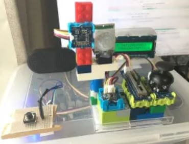
Arduino BoomBox
- Make a Boombox out of your shoe box using a potentiometer and a combination of several simple modules!
Raspberry Pi Music Server
- Make your own music player which can be controlled by a joystick, button and gesture where the volume can also be controlled with a slider!
Arduino BeatBox
- Create your own Beatbox using home-made capacitive touch sensors to trigger MP3 drum sounds!
Something to note when picking a potentiometer for your project, do consider these various factors: Humidity, Operating Temperature, Contamination and Seals, Shock and Vibration and Lifecycle to pick the best potentiometer for your project!
Summary
That’s all for today! To summarise, the Potentiometer
- 4 different types: Rotary, Linear, Digital and Rheostat.
- 2 functions: Potentiometer and Rheostat
- 2 different tracks: Linear and Logarithmic
If you have any questions about the potentiometer, please leave them down in the comments below!
Looking for other resistors other than potentiometers? Here at Seeed, wee also offer a RESK – Resistor Kit to suit your project needs!