How to Enable LoRa and LoRaWAN on Arduino and Raspberry Pi
Building an Arduino or Raspberry Pi project that needs to send data back and forth? Wi-Fi would work fine for that. But what if you need to transmit data over a long-range, yet do not wish to invest a lot in Wi-Fi setup of a large number of routers, access points, and network security programs? Introducing LoRa and LoRaWAN, which enable secure, low-cost radio communication over massive distances of up to 20km!
In this article, we will learn about how to use LoRa and LoRaWAN with Arduino and Raspberry Pi! This blog will cover:
- What is LoRa and LoRaWAN?
- LoRa vs LoRaWAN – What is the difference?
- Why use LoRa and LoRaWAN Technology?
- Choosing a LoRa Development Platform
- Tutorial: Getting Started with LoRa on Arduino
- Tutorial: LoRaWAN with Raspberry Pi and Arduino
Before we begin…
This article is one of many extensive blog posts that we’ve written on LoRa & LoRaWAN! Each of them is focused on a specific topic and is specially intended to help you better understand the two, so be sure to check them for a comprehensive insight!
- A Gentle Introduction to LoRaWAN Gateways & Nodes
- LoRaWAN Gateways – What You Need to Know!
- What is Peer-To-Peer (P2P) LR Communication?
- Enhance LR Communication with a LR Antenna!
- LoRa & LoRaWAN: Vertical Solutions for the Real World
- Create your own low-code IoT Application with SenseCAP LoRaWAN Devices on Datacake!
What is LR and LoRaWAN?
LoRa
Short for Long Range, LoRa is a spread spectrum modulation technique derived from chirp spread spectrum technology. It features long-range, low-power, and secure data transmission for your IoT applications. For example, they can be used to connect sensors, gateways, machines, devices, and even people wirelessly to the cloud.
LR operates in various frequency bands which range depending on the region. For example, the US operates in the 915 MHz band, Asia operates in the 865 to 867 MHz and 920 to 923 MHz band.
LoRaWAN
LoRaWAN is a Low Power, Wide-Area (LPWA) networking protocol that wirelessly connects battery-operated devices in a regional, national, or global network. Specifically, it targets IoT needs like secure bi-directional communication, mobility, and localization services by leveraging on unlicensed radio spectrum in the industrial, scientific, and medical (ISM) band.

The network architecture of LoRaWAN is laid out in a star-of-stars topology where LoRaWAN Gateways act as transparent bridges that relay messages between End Nodes and a Central Network Server in the back end as seen in the image above. Gateways are connected to a network server via a Standard IP connection and end devices use single-hop wireless communication with one or many gateways.
LoRa vs LoRaWAN – What is the difference?
While LoRa & LoRaWAN are commonly mistaken to be the same thing, they represent different components of a LoRa-based communication system that serve distinct functions.
LoRa is a radio frequency carrier signal based on the physical (PHY) layer that converts the data it receives to signals through modulation. On the other hand, LoRaWAN is a protocol located in the Media Access Control (MAC) layer that promotes LR signals to wider applications, designed for large-scale public networks with a single operator. LoRaWAN can also work in different frequencies by just connecting the right antenna to its socket.
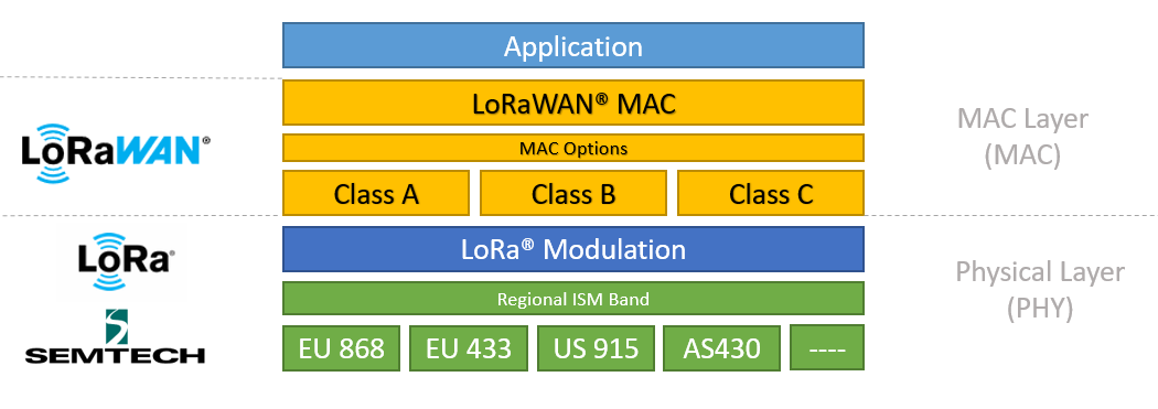
In simple terms, you can understand LR to be a type of hardware that supports long-range wireless communication, whereas LoRaWAN refers to a network protocol based on LR.
Why use LoRa and LoRaWAN Technologies?
There are several advantages of using LoRa and LoRaWAN technology.
Long Range
LoRa enables wireless communication over far longer ranges compared to Wi-Fi or BLE.
Low Power
Compared to WiFi, BLE or Satellite Communication, devices in a LoRa network consume relatively little power. This allows them to run on renewable energy (eg. Solar power), and reduces battery replacement costs. Edge nodes can run on a single battery for up to years.
Secure
LoRaWAN networks are protected by end-to-end AES128 encryption, mutual authentication, integrity protection, and confidentiality.
Standardized
LoRa & LoRaWAN are widely accepted technologies and protocols, allowing you to capitalize on device interoperability and global availability of LoRaWAN networks for rapid and convenient deployment of IoT applications anywhere.
Low Cost
LoRa operates on unlicensed frequency spectrums, which reduces fees for network operations. In addition, a wide variety of pre-licensed LoRa development platforms reduces legislative costs.
Flexible
LoRa & LoRaWAN combine the best of other technologies and can be used in a variety of environments and networks. Like Wi-Fi, LoRaWAN operates in the unlicensed band and supports indoor applications; like Cellular, LoRa Technology is highly secure from end devices to the application server, and is suitable for outdoor applications.
Choosing a LoRa Development Platform
At this point, you might be wondering how you can get your hands on LoRa & LoRaWAN for building your own IoT projects. Well. you’ll be glad to know that Seeed offers a variety of LoRa development platforms for every purpose, especially our latest LoRa solutions!
In this section, I’ll be sharing my top product recommendations for getting started with LoRa & LoRaWAN!
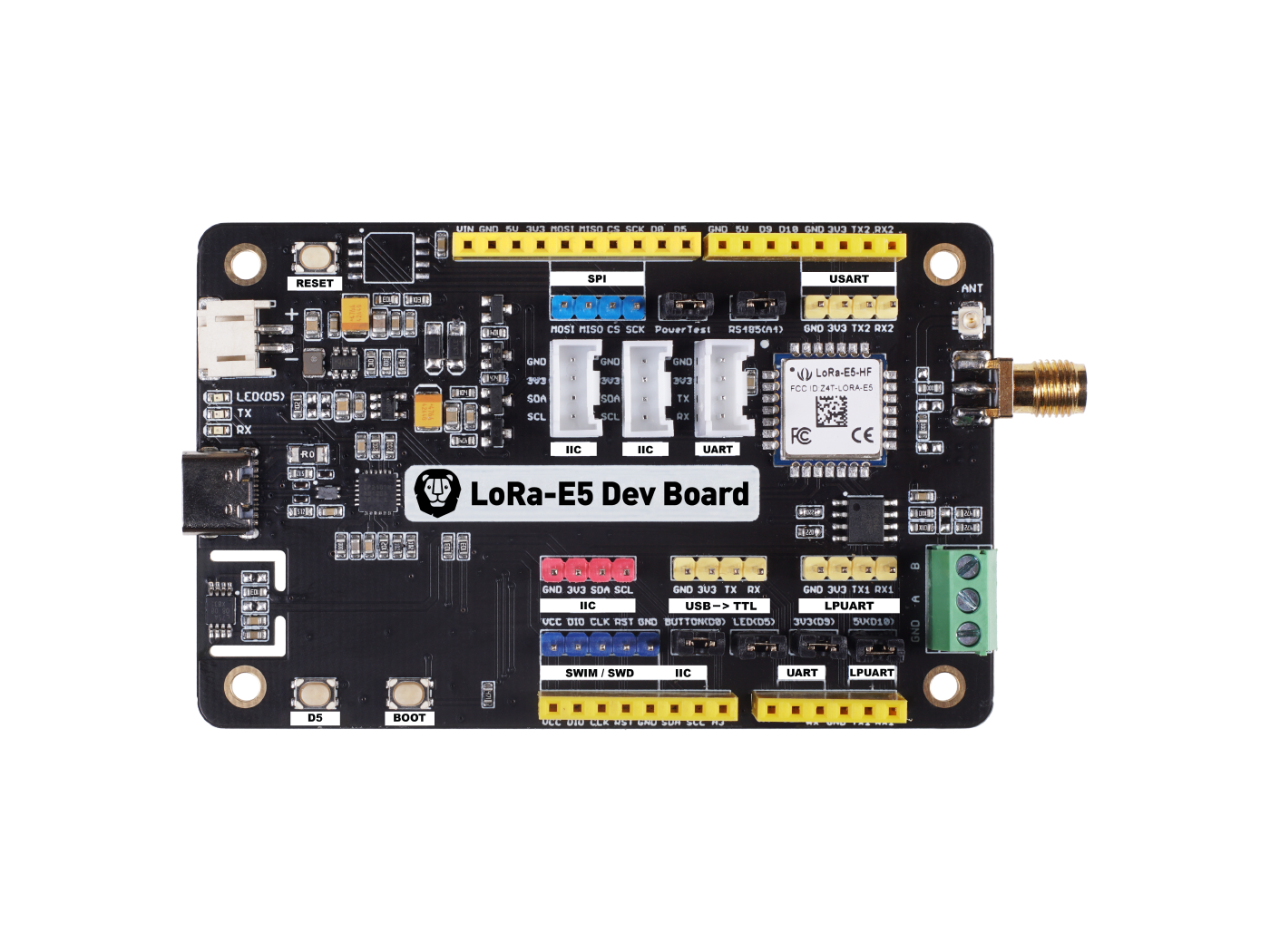
Wio E5 Development Kit
The Wio E5 Development Kit consists of the Wio E5 Development board, an antenna, a USB Type C Cable and a 2*AA 3V Battery Holder. The Wio E5 Dev Board is embedded with the Wio E5 STM32WLE5JC module with LoRaWAN protocol compatibility on the global frequency band. In addition, it supports various data protocols and interfaces, such as full GPIOs, RS-485 and Grove!
Product Features:
- Ultra-low power consumption and high performance
- Easy testing and rapid prototyping
- Full GPIOs that lead out to rich interfaces, including RS-485, Grove, and etc.
- Global LoRaWAN® and LR frequency plan supported
- Long-distance transmission range to 10km (ideal value in open area)
If you’re keen to pick up the Wio E5 Development Kit, visit the Seeed Online Store now!
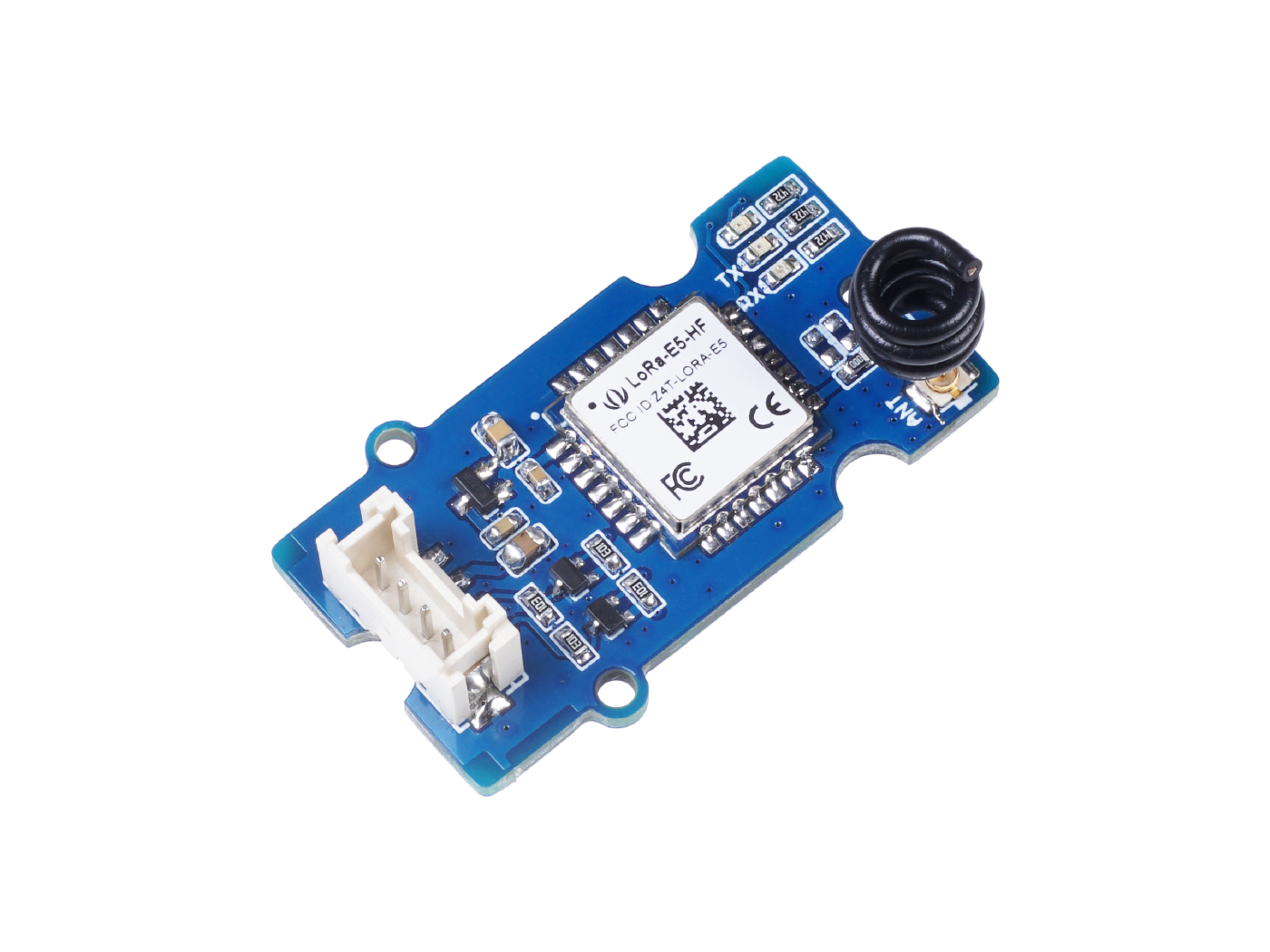
Grove – Wio E5 (STM32WLE5JC)
If you want to use LoRa with an SBCs like the popular Raspberry Pi 4, or an Arduino microcontroller like the Wio Terminal, the Wio E5 Grove module will be your best bet. Featuring full LoRaWAN capabilities in the modular simplicity of the Grove ecosystem, the Grove Wio E5 lets you bring your existing devices into your LoRaWAN network with just a few simple steps!
Core Features:
- Wio E5 (STM32WLE5JC) embedded
- Support LoRaWAN protocol on EU868/US915 frequency band
- Ultra-long transmitting range up to 10km (Ideal value in open space)
- Easy control by AT command via UART connection
- Rapid prototyping with plug-and-play Grove interfaces
- Ultra-low power consumption and high performance
Visit the Seeed Online Store to learn more about the Grove Wio E5 Module today!
Wio-E5 & Wio-E5-LE (STM32WLE5JC) LoRa Module
For those who want to custom design your LoRa-powered PCBAs, I highly recommend checking out our STM32WLE5JC-powered LoRa modules: the Wio-E5 and Wio-E5-LE, which are the world-first combo of LoRa RF and MCU integrated in one single tiny module! Coming with CE, FCC, TELEC certifications, and built-in AT Command, these two modules are production-ready to scale up your LoRa products.

Highlight features:
- STMicroelectronics’ STM32WLE5JC embedded
- Built-in AT command & ST SDK for further development
- Ultra-low power consumption down to 26 mA In transmit mode
- Equipped with a variety of GPIO interfaces (UART, I2C, and ADC) for peripherals expansion
- Ultra-long transmitting range up to 10km (Ideal value in open space)
Visit the Seeed Online Store to learn more about the Wio-E5 LoRa Module today!
Note: A full LoRa system will require four key components: End nodes, gateway, network serve and application server. For our full list of products for each category, please visit their corresponding links!
- LoRa Modules
- LoRa Dev Boards & Dev Kits
- LoRa Sensor Nodes (Devices)
- LoRa Gateways
- LoRa Accessories
- Industrial-grade LoRaWAN Products for Outdoor Applications
Tutorial: Getting Started with LoRa on Arduino
With this tutorial, I’d like to show you how to easily create low-power yet powerful applications in your smart home or IoT projects!
Note: LoRa is not suitable for projects that require large amounts of data to be transmitted at high rates.
You can use LR in two ways:
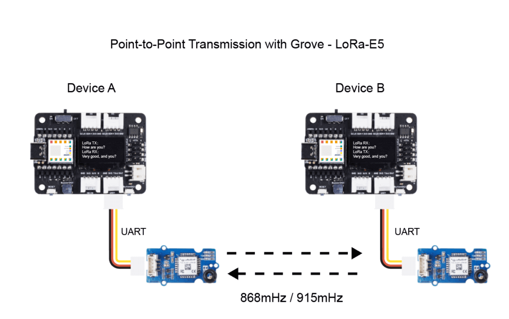
- Point-to-point communication
- Network (Building a LoRa network using LoRaWAN)
In today’s tutorial, we will be setting up our Edge Node with our XIAO SAMD21 and Grove DHT11 Temperature and Humidity Sensor to send data to our server on The Things Network.

Required Materials
- Seeed Studio XIAO SAMD21 SAM (Fully Arduino Compatible)
- XIAO Expansion Board
- Grove – Wio-E5 (STM32WLE5JC), EU868/US915, LoRaWAN supported
- Grove – DHT11 Temperature & Humidity Sensor
Hardware Connection
Step 1: Connect the Wio-E5 module directly to the “UART” slot of the Expansion Board.
Step 2: Connect the DHT11 into the “A0/D0” socket as shown below.
Software Preparation
If this is the first time you work with Arduino, we strongly recommend you to see Getting Started with Arduino before the start. Click to learn details about how to install an Arduino Library
Step 1: Install the u8g2 library
Step 2: Install the DHT sensor library
Step 3: Copy the following code into a new Arduino Sketch and upload.
#include <Arduino.h>
#include <U8x8lib.h>
#include "DHT.h"

#define DHTPIN 0 // what pin we're connected to

// Uncomment whatever type you're using!
#define DHTTYPE DHT11 // DHT 11
// #define DHTTYPE DHT22   // DHT 22  (AM2302)
//#define DHTTYPE DHT21   // DHT 21 (AM2301)

DHT dht(DHTPIN, DHTTYPE);

U8X8_SSD1306_128X64_NONAME_HW_I2C u8x8(/* reset=*/U8X8_PIN_NONE);
// U8X8_SSD1306_128X64_NONAME_SW_I2C u8x8(/* clock=*/ SCL, /* data=*/ SDA, /* reset=*/ U8X8_PIN_NONE);   // OLEDs without Reset of the Display

static char recv_buf[512];
static bool is_exist = false;
static bool is_join = false;
static int led = 0;

static int at_send_check_response(char *p_ack, int timeout_ms, char *p_cmd, ...)
{
    int ch;
    int num = 0;
    int index = 0;
    int startMillis = 0;
    va_list args;
    memset(recv_buf, 0, sizeof(recv_buf));
    va_start(args, p_cmd);
    Serial1.printf(p_cmd, args);
    Serial.printf(p_cmd, args);
    va_end(args);
    delay(200);
    startMillis = millis();

    if (p_ack == NULL)
    {
        return 0;
    }

    do
    {
        while (Serial1.available() > 0)
        {
            ch = Serial1.read();
            recv_buf[index++] = ch;
            Serial.print((char)ch);
            delay(2);
        }

        if (strstr(recv_buf, p_ack) != NULL)
        {
            return 1;
        }

    } while (millis() - startMillis < timeout_ms);
    return 0;
}

static void recv_prase(char *p_msg)
{
    if (p_msg == NULL)
    {
        return;
    }
    char *p_start = NULL;
    int data = 0;
    int rssi = 0;
    int snr = 0;

    p_start = strstr(p_msg, "RX");
    if (p_start && (1 == sscanf(p_start, "RX: \"%d\"\r\n", &data)))
    {
        Serial.println(data);
        u8x8.setCursor(2, 4);
        u8x8.print("led :");
        led = !!data;
        u8x8.print(led);
        if (led)
        {
            digitalWrite(LED_BUILTIN, LOW);
        }
        else
        {
            digitalWrite(LED_BUILTIN, HIGH);
        }
    }

    p_start = strstr(p_msg, "RSSI");
    if (p_start && (1 == sscanf(p_start, "RSSI %d,", &rssi)))
    {
        u8x8.setCursor(0, 6);
        u8x8.print("                ");
        u8x8.setCursor(2, 6);
        u8x8.print("rssi:");
        u8x8.print(rssi);
    }
    p_start = strstr(p_msg, "SNR");
    if (p_start && (1 == sscanf(p_start, "SNR %d", &snr)))
    {
        u8x8.setCursor(0, 7);
        u8x8.print("                ");
        u8x8.setCursor(2, 7);
        u8x8.print("snr :");
        u8x8.print(snr);
    }
}

void setup(void)
{
    u8x8.begin();
    u8x8.setFlipMode(1);
    u8x8.setFont(u8x8_font_chroma48medium8_r);

    Serial.begin(115200);
    pinMode(LED_BUILTIN, OUTPUT);
    digitalWrite(LED_BUILTIN, HIGH);

    Serial1.begin(9600);
    Serial.print("E5 LORAWAN TEST\r\n");
    u8x8.setCursor(0, 0);

    if (at_send_check_response("+AT: OK", 100, "AT\r\n"))
    {
        is_exist = true;
        at_send_check_response("+ID: AppEui", 1000, "AT+ID\r\n");
        at_send_check_response("+MODE: LWOTAA", 1000, "AT+MODE=LWOTAA\r\n");
        at_send_check_response("+DR: EU868", 1000, "AT+DR=EU868\r\n");
        at_send_check_response("+CH: NUM", 1000, "AT+CH=NUM,0-2\r\n");
        at_send_check_response("+KEY: APPKEY", 1000, "AT+KEY=APPKEY,\"2B7E151628AED2A6ABF7158809CF4F3C\"\r\n");
        at_send_check_response("+CLASS: C", 1000, "AT+CLASS=A\r\n");
        at_send_check_response("+PORT: 8", 1000, "AT+PORT=8\r\n");
        delay(200);
        u8x8.setCursor(5, 0);
        u8x8.print("LoRaWAN");
        is_join = true;
    }
    else
    {
        is_exist = false;
        Serial.print("No E5 module found.\r\n");
        u8x8.setCursor(0, 1);
        u8x8.print("unfound E5 !");
    }

    dht.begin();

    u8x8.setCursor(0, 2);
    u8x8.setCursor(2, 2);
    u8x8.print("temp:");

    u8x8.setCursor(2, 3);
    u8x8.print("humi:");

    u8x8.setCursor(2, 4);
    u8x8.print("led :");
    u8x8.print(led);
}

void loop(void)
{
    float temp = 0;
    float humi = 0;

    temp = dht.readTemperature();
    humi = dht.readHumidity();

    Serial.print("Humidity: ");
    Serial.print(humi);
    Serial.print(" %\t");
    Serial.print("Temperature: ");
    Serial.print(temp);
    Serial.println(" *C");

    u8x8.setCursor(0, 2);
    u8x8.print("      ");
    u8x8.setCursor(2, 2);
    u8x8.print("temp:");
    u8x8.print(temp);
    u8x8.setCursor(2, 3);
    u8x8.print("humi:");
    u8x8.print(humi);

    if (is_exist)
    {
        int ret = 0;
        if (is_join)
        {

            ret = at_send_check_response("+JOIN: Network joined", 12000, "AT+JOIN\r\n");
            if (ret)
            {
                is_join = false;
            }
            else
            {
                at_send_check_response("+ID: AppEui", 1000, "AT+ID\r\n");
                Serial.print("JOIN failed!\r\n\r\n");
                delay(5000);
            }
        }
        else
        {
            char cmd[128];
            sprintf(cmd, "AT+CMSGHEX=\"%04X%04X\"\r\n", (int)temp, (int)humi);
            ret = at_send_check_response("Done", 5000, cmd);
            if (ret)
            {
                recv_prase(recv_buf);
            }
            else
            {
                Serial.print("Send failed!\r\n\r\n");
            }
            delay(5000);
        }
    }
    else
    {
        delay(1000);
    }
}
TTN Console Configuration Setup
In this section, we set up our console and application on The Things Network to visualise the data from our XIAO SAMD21.
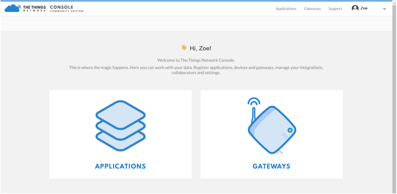
Step 1: Head over to the TTN website and create your account. Navigate to “Console”, then click on “APPLICATIONS”.
Step 2: Add an Application.
- Application ID: Enter a unique application name.
- Description: Enter a description.
- Handler Registration: Select the same handler as the gateway router.
- Select Add Application to continue.

Step 3: Add a decoding script to the application and save.

Copy and paste the decoding function below.
function Decoder(bytes, port) {

  var decoded = {};
  if (port === 8) {
    decoded.temp = bytes[0] <<8 | bytes[1];
    decoded.humi = bytes[2] <<8 | bytes[3];
  }

  return decoded;
}
Step 4: Add the Grove – Wio-E5 device to the TTN Console.
First, we have to retrieve some module information. Run the downloaded program module, view the DEVEUI and APP EUI of the Wio-E5 module through the serial port (USB).

Add these two EUIs to your TTN Network through Settings > EUIs > Add EUI.

Step 5: Register Device by navigating to Devices > Register Device.

- Device ID: Enter a unique name.
- Device EUI: Select the E5 dev EUI.
- APP KEY: Use this APPkey 2B7E151628AED2A6ABF7158809CF4F3C
- App EUI: Select the E5 App EUI.

Step 6: Perform Gateway Registration on TTN Console.
Please refer to the instructions shown in The Things Indoor Gateway wiki page: The Things Indoor Gateway Get Started with SenseCAP.

Step 7: Review the Result. You can check the readings via the Serial Monitor.

Temperature and Humidity Parameters
As the final step in setting up your Grove – Wio E5 module, we will demonstrate how you can visualise the temperature and humidity data that is being remotely transmitted to TTN.
Step 1: Enter the APPLICATION created in TTN and click on the data page to view the reported data.

Step 2: Remote Control Example with LED
You can also send commands to control your Edge Node through the TTN application console. In this example, we will be controlling the LED on the Seeeduino XIAO by sending commands through a downlink payload.
First, enter the current device control page. Send the specified data in the “DOWNLINK” window. Send “01” to turn on LED light; Send “00” to turn it off. You can add more functionality to your Edge Node by programming it into the uploaded Arduino Sketch.

And that concludes this basic tutorial on how to connect a LoRa Edge Node with a Seeed Studio XIAO SAMD21 to send data remotely in a LoRaWAN Network! In the next section, we will go further in-depth to create our very own LoRaWAN.
LoRaWAN with Raspberry Pi and Arduino Tutorial
A typical LoRa network consists of 4 parts: Edge / End Node Devices (eg. Sensors, Radio Module), Gateways, a network service, and an application. Similar to a Wi-Fi network, a LoRaWAN network can only be set up with both devices and gateways. LoRaWAN Gateways help to scan the spectrum and capture LR packets.
A unique feature of LoRaWAN network infrastructure is that no devices are associated with a single gateway. This allows all gateways within range of a device to receive its signal and forward the data to a network service that handles the packet. The network service acts as the entity that speaks LoRaWAN to the gateway, which gets the data to the application. They also handle other LR features like adaptive data rating. After that, the network service will then forward the decrypted data to your application where it will be processed.
Through this second tutorial, you will learn how to build your own complete private LoRaWAN network with Arduino and Raspberry Pi!
Required Materials
To follow along with this tutorial, you can acquire all the required materials in a complete package with the LoRa /LoRaWAN Gateway – 868MHz Kit with Raspberry Pi 3. This Kit provides all the basic elements to build a LoRaWAN Network, containing:
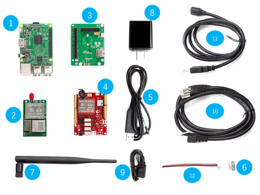
| No. | Parts |
| 1 | 1 x Raspberry Pi 3 |
| 2 | 1 x Gateway module RHF0M301–868 |
| 3 | 1 x PRI 2 Bridge RHF4T002 |
| 4 | 1 x Seeeduino LoRaWAN with GPS (RHF76-052AM) |
| 5 | 1 x USB to UART Adapter |
| 6 | 1 x Upgrade to 16GB Micro SD Card – Class 10 |
| 7 | 1 x 0dBi Rubber Duck Antenna |
| 8 | 1 x 5V/2.1A American Standard Adapter with Micro USB Connector |
| 9 | 1 x Micro USB Cable 20cm |
| 10 | 1 x Micro USB Cable 100cm |
| 11 | 1 x RJ45 Ethernet Cable 200cm |
| 12 | 1 x JST2.0 Cable 10cm |
We have also recently released the WM1302 Pi Hat for building powerful LoRaWAN Gateways with the WM1302 LoRaWAN Gateway Modules on the Raspberry Pi. The new WM1302 series is based on the latest Semtech SX1302, which brings improvements across the board in transmission power, thermal management and power efficiency.
We are currently in the midst of preparing a tutorial with the new WM1302 Pi Hat. Meanwhile, kindly visit its product page to learn more!
Step by Step tutorial: Build your own LR Network using LoRaWAN
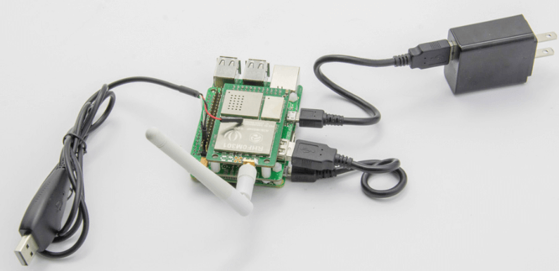
Hardware Setup
Since there are many interfaces here, let’s first go over their capabilities.

Step 1: Plug Gateway module RHF0M301–868 into PRI 2 Bridge RHF4T002.
Step 2: Plug PRI 2 Bridge RHF4T002 into Raspberry Pi 3.
Step 3: Connect ❷ and ❸ via a 20cm Micro-USB cable.
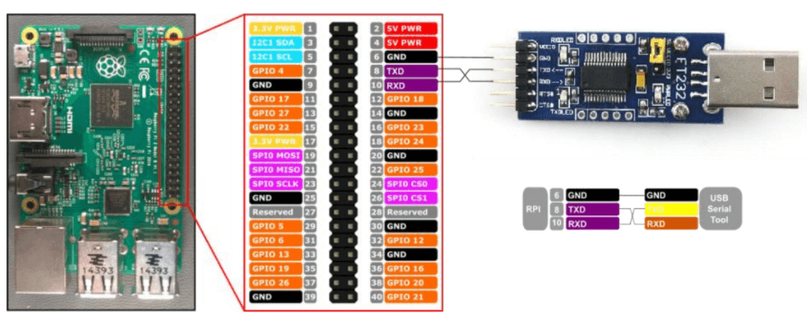
Step 4: Connect the USB to UART Adapter to the GPIO of Raspberry Pi 3. Please connect them as the picture shown below.
Step 5: Plug the USB to UART Adapter into your PC.
Step 6: Connect ❶ with 5V/2.1A Standard Adapter via 100cm Micro-USB cable.
Your hardware connection should look like this:
Software Setup
Before starting, take note that you will need the following software on your computer:
- Arduino IDE – Portable serial tool for Serial Communication with the Seeeduino LoRaWAN with GPS.
- PuTTY – Terminal tool with both serial and SSH capabilities to control our Raspberry Pi.
Connecting to Local Server
Step 1: Power up the Raspberry Pi and connect to PuTTY.
First, make sure the serial tool and RPi (RHF4T002 Adapter) are connected correctly. Plug the FT232 tool into your PC (If COM port is not recognized correctly, please refer to Virtual COM Port Drivers).
Open Device Manager of your PC to get the right COM port. Like COM15 for example. Configure ExtraPuTTY according to below picture (Speed 115200, others use defaults), click Open. As the gateway is still not opened, so there is nothing in the terminal.

Power the gateway up. The booting log will be showed in the PuTTY terminal. When complete, you will be prompted to input your login name. (This may take 1 – 2 minutes to complete)

Login with the RHF2S001’s default username and password (Username: rxhf, Password: risinghf ). Then, connect the RHF2S001 with the router through ethernet cable and run ifconfig to check the IP address and MAC address.

IP IS IN THE BLUE SQUARE, MAC ADDRESS IS IN ORANGE SQUARE (FORMAT: B8:27:EB:XX:XX:XX)
To login through SSH, you need to fill in the Hostname with the IP address you’ve just got and use port 22 where you will choose the SSH connection type. Just leave the other options by default. Then simply click Open. (We are using SSH as it is faster and more stable compared to Ethernet and UART.
Step 2: Expand SD Card File System
By default, the image enables only 2GB for Raspbian System. It is recommended to expand the filesystem to use the entire SD card instead. Run the below command in the PuTTY terminal to start raspi-config.
sudo raspi-configChoose “Expand Filesystem”, when finished reboot to make it effect. Run below command in the PuTTY terminal to know the SD card capacity and usage.
df -hPlease refer to Raspberry Pi Foundation’s raspi-config tool documentation for more details.
Step 3: Use RHF2S001 integrated LoRaWAN server
Connect Gateway with the internal server by running the following commands in the PuTTY terminal and check the status:
sudo systemctl status pktfwd
If pktfwd service is not active, run the following command to start it:
sudo systemctl enable pktfwd
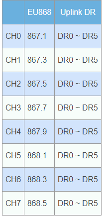
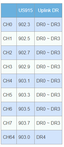
sudo systemctl restart pktfwdHere is the Frequency Plan for EU868,
and the Frequency Plan for US915 HYBRID.
Now, we will configure Seeeduino LoRaWAN’s settings by first connecting the it to the PC. Then, open the Arduino IDE and copy the code below into a new sketch.
 void setup()
 {
     Serial1.begin(9600);
     SerialUSB.begin(115200);
 }

 void loop()
 {
     while(Serial1.available())
     {
         SerialUSB.write(Serial1.read());
     }
     while(SerialUSB.available())
     {
         Serial1.write(SerialUSB.read());
     }
 }
Next, choose the appropriate serial port for the Seeeduino LoRaWAN and upload the code.

Now, open the serial monitor in the upper right corner (or press Ctrl+Shift+M). Check Newline (This option will add “\r\n” at the end of each command), set the baud rate 9600, then enter the commands below and press send.

For EU868:
AT+FDEFAULT=RISINGHF
AT+DR=EU868
For US915:
AT+FDEFAULT=RISINGHF
AT+DR=US915HYBRID
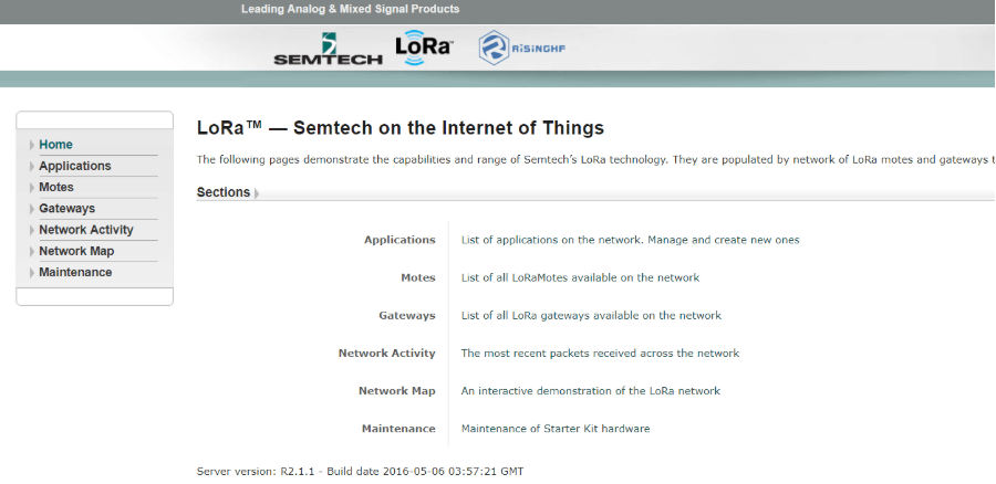
AT+RXWIN2=923.3,DR8Now, we will be accessing the internal server console. Enter the IP address of your LoRaWAN Gateway into your browser; you should be taken to the following page.
Step 4. Use Seeeduino LoRaWAN GPS to access the LoRaWAN server
There are two modes of LoRaWAN Communication. In this tutorial, we will only talk about the ABP Mode since it is free for use. For more information about the OTAA Mode, (which is for commercial use), kindly visit here.
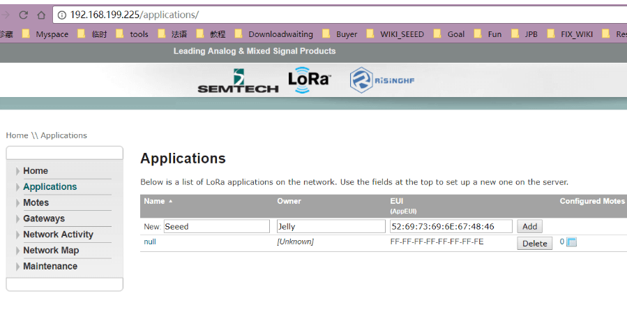
First find the “Application” button in the upper right corner of the website above, click it and you will see a new page.
Now you need the APPEui, DevAddr, DevEui of the Seeeduino LoRaWAN to add a new application. To retrieve this information, send the following AT command through the Arduino serial monitor.
at+id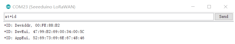
Fill in the blank with your ID information, as well as the name and owner according to your preference. Then click Add.
You will be brought to the configure page, where you should select Personalised Motes.
Fill in the DevEUI and DevAddr with ID info. of your Seeeduino LoRaWAN GPS and set the NWKSKEY and APPSKEY by default. You can refer to the picture below.
- DevEui: Seeeduino LoRaWAN GPS get through AT+ID command
- DevAddr: Seeeduino LoRaWAN GPS get through AT+ID command
- NWKSKEY:Default value 2B7E151628AED2A6ABF7158809CF4F3C
- APPSKEY:Default value 2B7E151628AED2A6ABF7158809CF4F3C

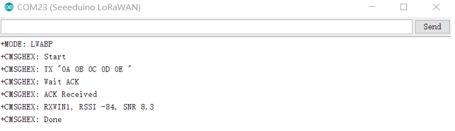
To test whether if the device has been added successfully, use the serial monitor of Arduino IDE to send the command below.
at+mode=lwabp

AT+CMSGHEX="0a 0b 0c 0d 0e"
The results should be as follows:
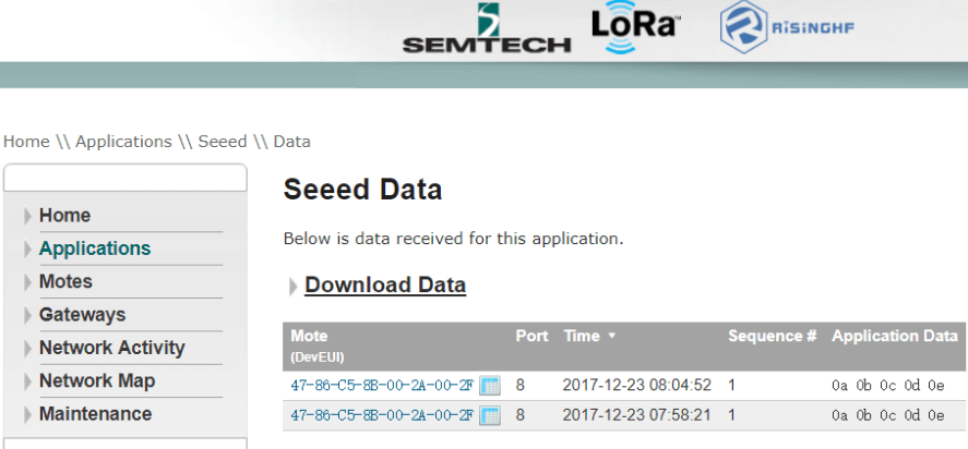
Then, return to the website and click Application->Seeed(the name of the Application you just added)->View application data where you will see the data you’ve just sent form the Seeeduino_LoRAWAN.
Still with us? Good! In our last step, you will learn how to connect to Loriot Server, which will act as your LoRaWAN network server provider.
Connect to Loriot Server
Step 1: Loriot Server Gateway Registration
If you are a new user, you will first need to register for an account. Follow the website instructions to activate your account. After successful activation, click here to log in. The default tier is “Community Network”, which supports 1 Gateway (RHF2S001) and 10 nodes.
Navigate to Dashboard > Gateway, and click Add Gateway begin adding your Gateway. Select Raspberry Pi 3, and enter the remaining settings as follows:
- Radio Front-End: RHF2S001 868/915 MHz(SX1257)
- Bus: SPI
- Enter the MAC address of your RHF2S001, (eg. b8:27:eb:xx:xx:xx)
- Input Gateway Location information
Click “Register Raspberry Pi gateway” to finish the registration.

Click the registered gateway to enter configuration page, switch “Frquency Plan” manually, your plan here is decided by the type of your RHF2S001 type. The available plans are CN470, CN473, CN434, CN780 and EU868. After selecting, refresh the page to get the desired channel. In this example, we will use EU868. Then, run the command in the PuTTY terminal.
cd /home/rxhf/loriot/1.0.2
sudo systemctl stop pktfwd
sudo gwrst
wget https://cn1.loriot.io/home/gwsw/loriot-risinghf-rhf2s008-rhf1257-SPI-0-latest.bin -O loriot-gw.bin
chmod +x loriot-gw.bin
./loriot-gw.bin -f -s cn1.loriot.io
Finish the gateway registration. You should now see the Gateway as Connected. Our next step will be to register the node.

Step 2. Loriot Server Connect Node device
Firstly, get the available gateway channels from Dashboard > Gateway > Your Gateway. The available channels should be shown in accordance with the picture below.

Next, configure the Seeeduino LoRAWAN GPS by opening the serial monitor of Arduino IDE and enter the command below.
at+chTo confirm the default channel of the Seeeduino_LoRAWAN GPS, you will get 3 channels. If there is no available channel, you can change the channels of Seeeduino_LoRAWAN by the command below.
at+ch=0,868.1
at+ch=1,868.3
at+ch=2,868.5
Check the channels again with the at+ch command.
Now, we will add Seeeduino_LoRAWAN GPS as an ABP Node with the Loriot server. Navigate to Dashboard > Applications > SimpleApp. Click Import ABP and enter the following fields.
- DevAddr: Seeeduino_LoRAWAN GPS get through “AT+ID” command
- FCntUp: Set to 1
- FCntDn: Set to 1
- NWKSKEY: Default value 2B7E151628AED2A6ABF7158809CF4F3C
- APPSKEY: Default value 2B7E151628AED2A6ABF7158809CF4F3C
- EUI: DEVEUI, Seeeduino_LoRAWAN GPS get through “AT+ID” command
Note: For the device address, Loriot doesn’t support colon connector so you will have to remove them manually.

Click Import Device to finish the device import. Now, navigate once again to Dashboard > Applications > SampleApp to verify the new ABP Node that you just created.

Lastly, we will test the connection by sending data from the Seeeduino_LoRAWAN by entering this following command:
AT+CMSGHEX="0a 0b 0c 0d 0e"Go to Dashboard > Applications > SampleApp > Device. Click the Node Device EUI or DevAddr, and you will find the data you’ve just sent here.

Congratulations! You’ve now set up your very own LoRaWAN End Node, Gateway and Server!
Summary
With LR and LoRaWAN, anyone can set up a network and transfer data over long distances with IoT devices in a manner that is both secure and low cost! that is secure and also low-cost! With this article, I hope that you have gained a better understanding of what LoRa and LoRaWAN networks are for as well as how to get started!
We also offer various LR and LoRaWAN products other than those stated above ranging from Gateways, Node, Arduino LR modules, Raspberry Pi LoRa and many more here!
If you are interested in LoRa projects? You can check out our LoRa IoTea project which is an automatic information collection system applied to a tea plantation! Alternatively, you can also visit our article on real-world solutions built with LoRa here!