What is an AMG8833? Features and Demo
AMG8833 might sound rather familiar to you if you’ve heard or used its predecessor, AMG883 before. In this blog, we will cover everything you need to know about AMG8833 as well as how you can set up for usage!
With that said, here is the content we’ll be covering:
- Overview of AMG8833
- AMG8833 Demo
- AMG8833 vs MLX90640 vs MLX90641
Overview of AMG8833
What is an AMG8833?

AMG8833 is Panasonic’s 8×8 IR Grid-Eye detector that contains eight rows of eight pixels each housing infrared thermopiles, capable of measuring blackbody radiation, around the thermal range of 8-15 microns.
Commonly used in the infrared thermal temperature sensor array, in which the AMG8833 would provide high precision for temperature detection. Apart from that, you can also find usage of the sensor in automatic doors/elevators and home applications like air-conditioners.
Features of AMG8833
- Temperature detection of the two-dimensional area: 8 × 8 (64 pixels)
- I2C output (capability of temperature value output)
- Temperature range of measuring object: 0 °C to 80 °C +32 °F to +176 °F
- Long detection distance
- Compact SMD package (adaptively to reflow mounting)
- RoHS compliant
- Supports both Arduino and Raspberry Pi
Specifications
| Dimensions | 40mm x20mm x6mm |
| Weight | G.W 10g |
| Battery | Exclude |
| Operating Voltage | 3.3V / 5V |
| Temperature range of measuring object | 0 °C to 80 °C +32 °F to +176 °F |
| Operating temperature range | 0 °C to 80 °C +32 °F to +176 °F |
| Storage temperature range | −20 °C to 80 °C –4 °F to +176 °F |
| Temperature accuracy | Typical ±2.5 °C ±4.5 °F |
| Viewing angle | Typical 60 ° |
| Optical axis gap | Within Typical ±5.6 ° |
| Number of pixels | 64 (Vertical 8 × Horizontal 8 Matrix) |
| External interface | I2C |
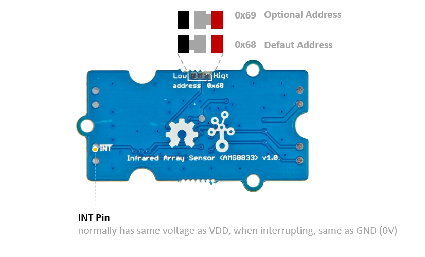
| I2C Address | 0x68(default) \ 0x69(optional) |
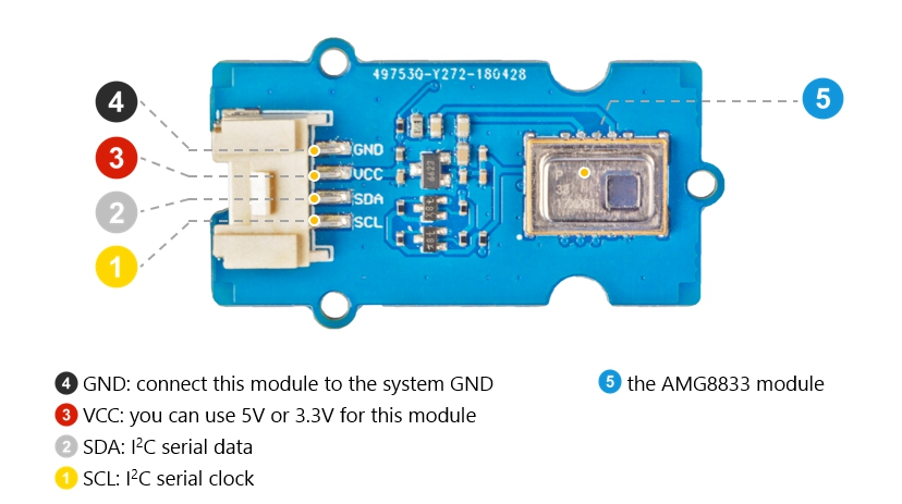
Pins
AMG8833 Demos
Now that we have some background knowledge about AMG8833, it’s time for us to learn how to set up for use! In our demos, we’ll be using our Grove – AMG8833 8×8 Infrared Thermal Temperature Sensor Array.
For Arduino
What you’ll need:
- Seeeduino V4.2 // Any Arduino compatible board
- Grove Base Shield V2.0 // Base shield
- Grove – AMG8833 8×8 Infrared Thermal Temperature Sensor Array
- 2.8 TFT Touch Shield V2.0 // Any display screen
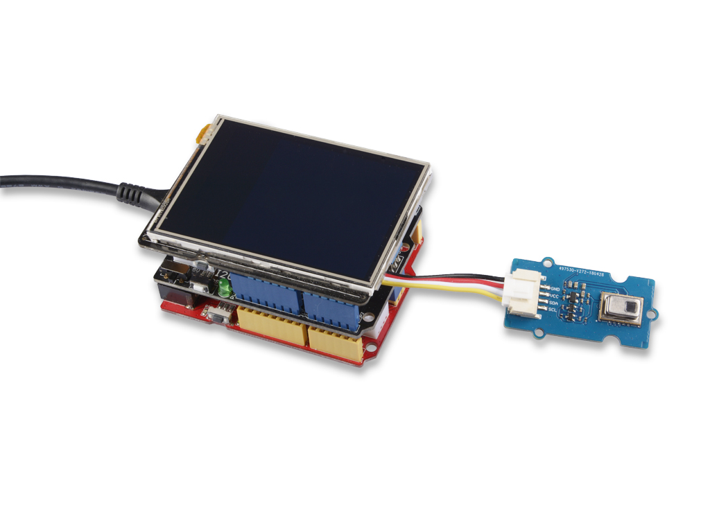
Steps for connecting Hardware:
Step 1: Connect the Grove – Infrared Temperature Sensor Array (AMG8833) to port I2C of Grove-Base Shield.
Step 2: Plug Grove – Base Shield into Seeeduino.
Step 3: Plug 2.8 TFT Touch Shield V2.0 into the Grove – Base Shield.
Step 4: Connect Seeeduino to PC via a USB cable.
Steps for working with software:
Step 1. Download the Seeed_AMG8833 Library from Github.
Step 2. Refer to How to install library for Arduino.
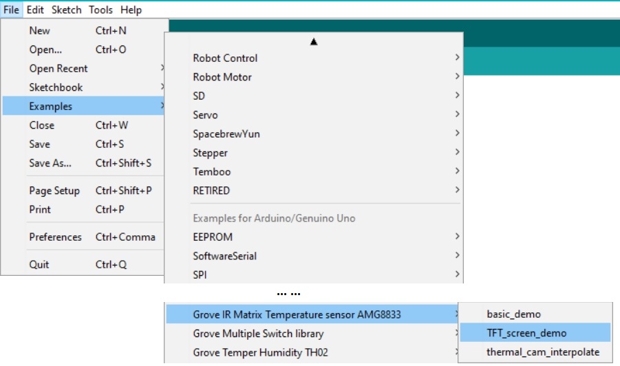
Step 3. Restart the Arduino IDE. Open the example, you can open it through these three ways:
a. Open it directly in the Arduino IDE via the path: File → Examples → Grove IR Matrix Temperature sensor AMG8833 → TFT_screen_demo.
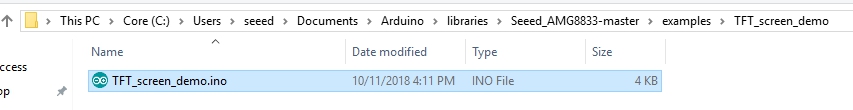
b. Open it in your computer by click the TFT_screen_demo.ino which you can find in the folder XXXXArduino\libraries\Seeed_AMG8833-master\examples\TFT_screen_demo, XXXX is the location you installed the Arduino IDE.
c. Or, you can just copy the following code into a new sketch in the Arduino IDE.
#include <stdint.h>
#include <TFTv2.h>
#include <SPI.h>

#include "Seeed_AMG8833_driver.h"


AMG8833 sensor;

#define TFT_PIXELS_NUM   30

void parse_int_status(u8* status)
{
    u8 val=0;
    for(u32 i=0;i<8;i++)
    {
        if(status[i])
        {
            for(u32 j=0;j<8;j++)
            {
                if(status[i]&((1<<j)))
                {
                    Serial.print("pixel ");
                    Serial.print(8*i+j+1);
                    Serial.println("interrupt is generated!!!");
                }
            }
        }
    }
}

void print_status(u8* status)
{
    for(u32 i=0;i<8;i++)
    {
        Serial.print(status[i],HEX);
        Serial.print("  ");

    }
    Serial.println("  ");
}


void setup()
{
    Serial.begin(115200);
    sensor.init();
    TFT_BL_ON;
    /*2.8 TFT screen. url:https://www.seeedstudio.com/2.8-TFT-Touch-Shield-V2.0-p-1286.html*/
    Tft.TFTinit();
}


void loop()
{
    u8 val=0;
    float pixels_temp[PIXEL_NUM]={0};
    u16 color[PIXEL_NUM]={0};
    /*Read temperature*/
    sensor.read_pixel_temperature(pixels_temp);
    /*Different temperature correspond to different color.*/
    for(u32 i=0;i<PIXEL_NUM;i++)
    {
        if(pixels_temp[i]<29)
        {
            color[i]=BLUE;
        }
        else if((pixels_temp[i]>=29)&&(pixels_temp[i]<30))
        {
            color[i]=GREEN;
        }
        else if((pixels_temp[i]>=30)&&(pixels_temp[i]<31))
        {
            color[i]=YELLOW;
        }
        else if((pixels_temp[i]>=31)&&(pixels_temp[i]<33))
        {
            color[i]=0xfd00;
        }
        else
        {
            color[i]=RED;
        }
    }
    /*Use a TFT screen to display.*/
    for(u32 i=0;i<PIXEL_NUM;i++)
    {
        Tft.fillScreen(TFT_PIXELS_NUM*(i%8),TFT_PIXELS_NUM*(i%8+1),TFT_PIXELS_NUM*(8-i/8),TFT_PIXELS_NUM*(7-i/8),color[i]);
    }
}
Step 4: Upload the demo. If you do not know how to upload the code, please check How to upload code.
If everything went well, you should be able to see this:
For Raspberry Pi
What you’ll need:
- Raspberry Pi 3 Model B // Or any Raspi compatible board
- Grove Base Hat for Raspberry Pi
- Grove – AMG8833 8×8 Infrared Thermal Temperature Sensor Array
- 5 inch 800×480 Capacitive TouchScreen // Or any display screen
Steps for connecting Hardware:
Step 1. Connect the Grove – Infrared Temperature Sensor Array (AMG8833) to port I2C of Grove Base Hat for Raspberry Pi.
Step 2. Plug Grove Base Hat for Raspberry Pi into Raspberry Pi.
Step 3. Connect the 5 inch 800×480 Capacitive TouchScreen with the Raspberry Pi via the HDMI cable.
Step 4. Connect Raspberry Pi to PC via a micro-USB cable, power the 5 inch 800×480 Capacitive TouchScreen via another micro-USB cable.
Steps for working with software:
Step 1. Open the I2C interface for your raspberry pi. You can open a terminal and tap the following command.
sudo raspi-config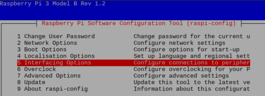
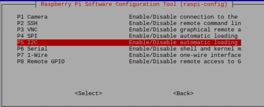
Step 2. When you see the picture above, choose Interfacing Options, then choose I2C to enable the I2C interface.
Step 3. When you finish, you can use the following command to check.
sudo i2cdetect -y 1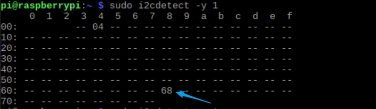
Once you’re able to see the I2C address, this means the raspberry has detected the sensor. If not, please repeat step1~3 again. Once that’s done, we can move on.
Step 4. Tap the following commands in the terminal to install related dependencies.
sudo apt-get update
sudo apt-get install -y build-essential python-pip python-dev python-smbus git
sudo apt-get install -y python-scipy python-pygame
sudo pip install colour
Step 5. Download the Seeed AMG8833 Python Library.
git clone https://github.com/Seeed-Studio/Seeed_AMG8833_Raspberry_Python.gitStep 6. Go into the AMG8833 folder, and run the demo.
pi@raspberrypi:~ $ cd Seeed_AMG8833_Raspberry_Python/
pi@raspberrypi:~/Seeed_AMG8833_Raspberry_Python $ ls
driver.py README.md Seeed_AMG8833.pyc
driver.pyc Seeed_AMG8833.py thermal_cam.py
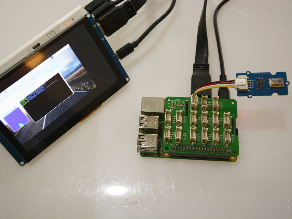
pi@raspberrypi:~/Seeed_AMG8833_Raspberry_Python $ python thermal_cam.py
If everything went well, you should be able to see this:

Building a IR Thermal Imaging Camera using Wio Terminal
What you’ll need:
Step 1. Install the LCD screen Library Seeed_Arduino_LCD, please visit Wio Terminal LCD for more information.
Step 2. Visit the Seeed_AMG8833 repositories and download the entire repo to your local drive. The Seeed_AMG8833 library can then be installed to the Arduino IDE.
Step 3. Open the Arduino IDE, and click sketch -> Include Library -> Add .ZIP Library, and choose the Seeed_AMG8833 file that you’ve have just downloaded.
Step 4. Plug in the Grove – Infrared Temperature Sensor Array (AMG8833) to the Grove I2C Interface of Wio Terminal.
Step 5. Download the Complete code here or copy the following and upload the code as follows:
/*


  This program is for upsizing an 8 x 8 array of thermal camera readings

  it will size up by 10x and display to a 240 x 320

  interpolation is linear and "good enough" given the display is a 5-6-5 color palet

  Total final array is an array of 70 x 70 of internal points only


  Revisions

  1.0     Kasprzak      Initial code

  1.1     Anson(Seeed Studio)  Adapted to Wio Terminal with Grove - Infrared Sensor(AMG8833)


*/


#include <Seeed_AMG8833_driver.h>

#include <TFT_eSPI.h>                // Include the graphics library (this includes the sprite functions)


TFT_eSPI    tft = TFT_eSPI();

TFT_eSprite Display = TFT_eSprite(&tft);  // Create Sprite object "img" with pointer to "tft" object

// the pointer is used by pushSprite() to push it onto the TFT


unsigned long CurTime;


uint16_t TheColor;

// start with some initial colors

uint16_t MinTemp = 25;

uint16_t MaxTemp = 35;


// variables for interpolated colors

byte red, green, blue;


// variables for row/column interpolation

byte i, j, k, row, col, incr;

float intPoint, val, a, b, c, d, ii;

byte aLow, aHigh;


// size of a display "pixel"

byte BoxWidth = 3;

byte BoxHeight = 3;


int x, y;

char buf[20];


// variable to toggle the display grid

int ShowGrid = -1;


// array for the 8 x 8 measured pixels

float pixels[64];


// array for the interpolated array

float HDTemp[80][80];


// create the camara object

AMG8833 ThermalSensor;


//Toggle the grid on and off

void toggleGrid() {

  ShowGrid = ShowGrid *-1;

  Display.fillRect(15, 15, 210, 210, TFT_BLACK);

  yield();

}


void setup() {

  Serial.begin(115200);


  // start the display and set the background to black

  tft.begin();

  tft.fillScreen(TFT_BLACK);


  //Interrupt to toggle Gird on and off

  pinMode(WIO_KEY_A, INPUT);

  attachInterrupt(digitalPinToInterrupt(WIO_KEY_A), toggleGrid, FALLING);


  // set display rotation (you may need to change to 0 depending on your display

  tft.setRotation(3);


  // show a splash screen


  tft.setCursor(20, 20);

  tft.setTextColor(TFT_BLUE, TFT_BLACK);

  tft.print("Thermal ");


  tft.setTextColor(TFT_RED, TFT_BLACK);

  tft.print("Camera");


  // let sensor boot up

  bool status = ThermalSensor.init();

  delay(100);


  if (!status) {

      Serial.print("Failed to initalized AMG8833");

  }


  // read the camera for initial testing

  ThermalSensor.read_pixel_temperature(pixels);


  // check status and display results

  if (pixels[0] < 0) {

    while (1) {

      tft.setCursor(20, 40);

      tft.setTextColor(TFT_RED, TFT_BLACK);

      tft.print("Readings: FAIL");

      delay(500);

    }

  }

  else {

    tft.setCursor(20, 40);

    tft.setTextColor(TFT_GREEN, TFT_BLACK);

    tft.print("Readings: OK");

    delay(2000);

  }


  tft.fillScreen(TFT_BLACK);


  Display.createSprite(TFT_HEIGHT, TFT_WIDTH);

  Display.fillSprite(TFT_BLACK);


  // get the cutoff points for the color interpolation routines

  // note this function called when the temp scale is changed

  Getabcd();


  // draw a legend with the scale that matches the sensors max and min

  DrawLegend();


}


void loop() {

  CurTime = millis();


  // draw a large white border for the temperature area

  Display.fillRect(10, 10, 220, 220, TFT_WHITE);


  // read the sensor

  ThermalSensor.read_pixel_temperature(pixels);


  // now that we have an 8 x 8 sensor array

  // interpolate to get a bigger screen

  // interpolate the 8 rows (interpolate the 70 column points between the 8 sensor pixels first)

  for (row = 0; row < 8; row ++) {

    for (col = 0; col < 70; col ++) {

      // get the first array point, then the next

      // also need to bump by 8 for the subsequent rows

      aLow =  col / 10 + (row * 8);

      aHigh = (col / 10) + 1 + (row * 8);

      // get the amount to interpolate for each of the 10 columns

      // here were doing simple linear interpolation mainly to keep performace high and

      // display is 5-6-5 color palet so fancy interpolation will get lost in low color depth

      intPoint =   (( pixels[aHigh] - pixels[aLow] ) / 10.0 );

      // determine how much to bump each column (basically 0-9)

      incr = col % 10;

      // find the interpolated value

      val = (intPoint * incr ) +  pixels[aLow];

      // store in the 70 x 70 array

      // since display is pointing away, reverse row to transpose row data

      HDTemp[ (7 - row) * 10][col] = val;


    }

  }


  // now that we have raw data with 70 columns

  // interpolate each of the 70 columns

  // forget Arduino..no where near fast enough..Teensy at > 72 mhz is the starting point


  for (col = 0; col < 70; col ++) {

    for (row = 0; row < 70; row ++) {

      // get the first array point, then the next

      // also need to bump by 8 for the subsequent cols

      aLow =  (row / 10 ) * 10;

      aHigh = aLow + 10;

      // get the amount to interpolate for each of the 10 columns

      // here were doing simple linear interpolation mainly to keep performace high and

      // display is 5-6-5 color palet so fancy interpolation will get lost in low color depth

      intPoint =   (( HDTemp[aHigh][col] - HDTemp[aLow][col] ) / 10.0 );

      // determine how much to bump each column (basically 0-9)

      incr = row % 10;

      // find the interpolated value

      val = (intPoint * incr ) +  HDTemp[aLow][col];

      // store in the 70 x 70 array

      HDTemp[ row ][col] = val;

    }

  }


  //display the 70 x 70 array

  DisplayGradient();


  //Crosshair in the middle of the screen

  Display.drawCircle(115, 115, 5, TFT_WHITE);

  Display.drawFastVLine(115, 105, 20, TFT_WHITE);

  Display.drawFastHLine(105, 115, 20, TFT_WHITE);


  //Push the Sprite to the screen

  Display.pushSprite(0, 0);


  //Displaying the temp at the middle of the Screen

  tft.setRotation(3);

  tft.setTextColor(TFT_WHITE);

  tft.drawFloat(HDTemp[35][35], 2, 90, 20);


  //Uncomment this to print out frame rate

  Serial.print("Frame rate: "); Serial.println(1/(0.001*(millis() - CurTime)));


}


// function to display the results

void DisplayGradient() {


  tft.setRotation(4);


  // rip through 70 rows

  for (row = 0; row < 70; row ++) {


    // fast way to draw a non-flicker grid--just make every 10 pixels 2x2 as opposed to 3x3

    // drawing lines after the grid will just flicker too much

    if (ShowGrid < 0) {

      BoxWidth = 3;

    }

    else {

      if ((row % 10 == 9) ) {

        BoxWidth = 2;

      }

      else {

        BoxWidth = 3;

      }

    }

    // then rip through each 70 cols

    for (col = 0; col < 70; col++) {


      // fast way to draw a non-flicker grid--just make every 10 pixels 2x2 as opposed to 3x3

      if (ShowGrid < 0) {

        BoxHeight = 3;

      }

      else {

        if ( (col % 10 == 9)) {

          BoxHeight = 2;

        }

        else {

          BoxHeight = 3;

        }

      }

      // finally we can draw each the 70 x 70 points, note the call to get interpolated color

      Display.fillRect((row * 3) + 15, (col * 3) + 15, BoxWidth, BoxHeight, GetColor(HDTemp[row][col]));

    }

  }


}


// my fast yet effective color interpolation routine

uint16_t GetColor(float val) {


  /*

    pass in value and figure out R G B

    several published ways to do this I basically graphed R G B and developed simple linear equations

    again a 5-6-5 color display will not need accurate temp to R G B color calculation


    equations based on

    http://web-tech.ga-usa.com/2012/05/creating-a-custom-hot-to-cold-temperature-color-gradient-for-use-with-rrdtool/index.html


  */


  red = constrain(255.0 / (c - b) * val - ((b * 255.0) / (c - b)), 0, 255);


  if ((val > MinTemp) & (val < a)) {

    green = constrain(255.0 / (a - MinTemp) * val - (255.0 * MinTemp) / (a - MinTemp), 0, 255);

  }

  else if ((val >= a) & (val <= c)) {

    green = 255;

  }

  else if (val > c) {

    green = constrain(255.0 / (c - d) * val - (d * 255.0) / (c - d), 0, 255);

  }

  else if ((val > d) | (val < a)) {

    green = 0;

  }


  if (val <= b) {

    blue = constrain(255.0 / (a - b) * val - (255.0 * b) / (a - b), 0, 255);

  }

  else if ((val > b) & (val <= d)) {

    blue = 0;

  }

  else if (val > d) {

    blue = constrain(240.0 / (MaxTemp - d) * val - (d * 240.0) / (MaxTemp - d), 0, 240);

  }


  // use the displays color mapping function to get 5-6-5 color palet (R=5 bits, G=6 bits, B-5 bits)

  return Display.color565(red, green, blue);


}


// function to get the cutoff points in the temp vs RGB graph

void Getabcd() {


  a = MinTemp + (MaxTemp - MinTemp) * 0.2121;

  b = MinTemp + (MaxTemp - MinTemp) * 0.3182;

  c = MinTemp + (MaxTemp - MinTemp) * 0.4242;

  d = MinTemp + (MaxTemp - MinTemp) * 0.8182;


}


// function to draw a legend

void DrawLegend() {


  //color legend with max and min text

  j = 0;


  float inc = (MaxTemp - MinTemp ) / 160.0;


  for (ii = MinTemp; ii < MaxTemp; ii += inc) {

    tft.drawFastHLine(260, 200 - j++, 30, GetColor(ii));

  }


  tft.setTextSize(2);

  tft.setCursor(245, 20);

  tft.setTextColor(TFT_WHITE, TFT_BLACK);

  sprintf(buf, "%2d/%2d", MaxTemp, (int) (MaxTemp * 1.8) + 32);

  tft.print(buf);


  tft.setTextSize(2);

  tft.setCursor(245, 210);

  tft.setTextColor(TFT_WHITE, TFT_BLACK);

  sprintf(buf, "%2d/%2d", MinTemp, (int) (MinTemp * 1.8) + 32);

  tft.print(buf);


}


// END OF CODE
Comparison between AMG8833, MLX90640 and MLX90641
We figured you might wonder how the AMG8833 would fare against similar sensors, thus here’s a table to illustrate their differences and similarities!
| Product | Pixel size | Temperature measurement range | Operating temperature |
| AMG8833 | 8 × 8 = 64 pixels | 0 °C to 80 °C | 0 °C to 80 °C |
| MLX90640 | 32 × 24=768 pixels | -40°C~+300°C | -40°C ~ +85°C |
| MLX90641 | 16 × 12=192 pixels | -40°C~+300°C | -40°C ~ +125°C |
As you can see, AMG8833’s specs when compared to the other thermal cameras are not spectacular, but it makes up for its long detection range and high precision! But if you’re going for higher image quality and larger temperature measurement range, MLX90640 and MLX90641 will do a better job at that.
If you’re interested in our MLX90640 and MLX90641, you can purchase them from us here:
- Grove – Thermal Imaging Camera – MLX90641 BCA 16×12 IR Array with 110° FOV
- Grove – Thermal Imaging Camera / IR Array MLX90640 110 degree
Summary
And that’s all on AMG3388! Hope that you have a better understanding of this sensor after reading this article! Do let us know how you feel about this product and you can purchase it through the links listed.
Should you require more resources related to MSG3388, do check out the links below!
Resources
- AMG8833 DATASHEET
- Seeed AMG8833 Arduino Library
- Seeed AMG8833 Python Library
- Grove – Infrared Temperature Sensor Array (AMG8833) Eagle Files