How to use Grove – 16-Channel PWM Driver (PCA9685) to Control Robotic Arm!
Have you ever encountered the situation where you want to build your own robotics projects using an Arduino, but failed to do so with only just an Arduino because of the limited number of PWM outputs it has?
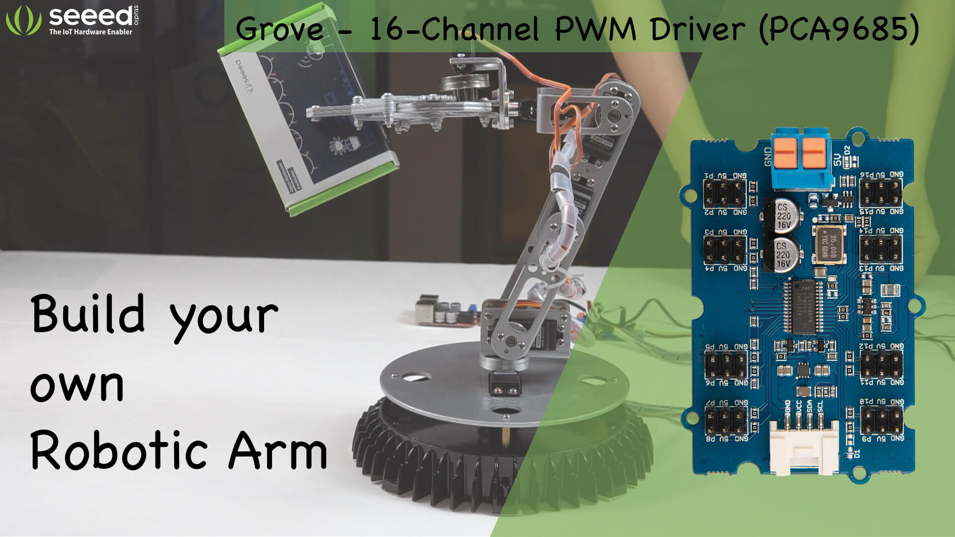
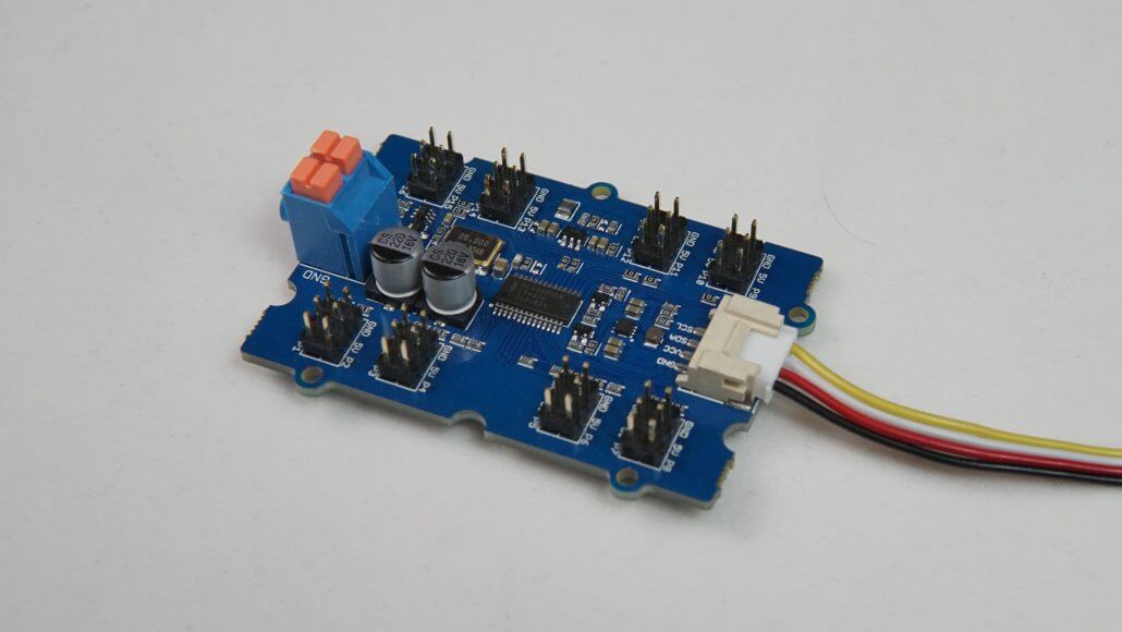
The solution to this will be to use a PWM driver such as the Grove – 16-Channel PWM Driver (PCA9685) which is a 12-bit PWM driver based on the NXP PCA9685 and can drive up to 16 servos with an external power supply of 5V. This PWM Driver can also be used to control LEDs.
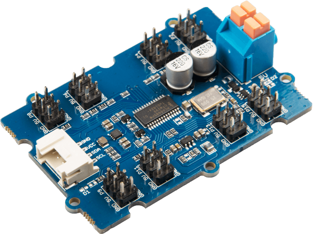
Grove – 16-Channel PWM Driver (PCA9685)
When you want to connect more than 16 servos at the same time, you can connect these drivers in series for up to 62 drivers which will be connected to the same I2C bus.
What is PWM?
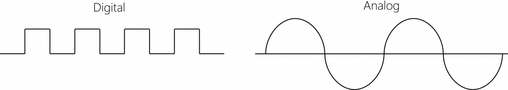
PWM stands for Pulse Width Modulation. Normally there are two different kinds of signals: Digital and Analog. Digital signals are “0” or “1”, “OFF” or “ON” and Analog signals can be ON, OFF or have an infinite number of positions between 0 and 1.
Computers can only understand 0’s and 1’s which is digital. So finally, the MCU (Microcontroller Unit) can only understand digital input. Once you have Analog inputs from your sensors, the Analog signals (ex: – from temperature sensors) have to be first translated into Digital signals through an Analog-to-digital converter and then the MCU can recognize that signal.
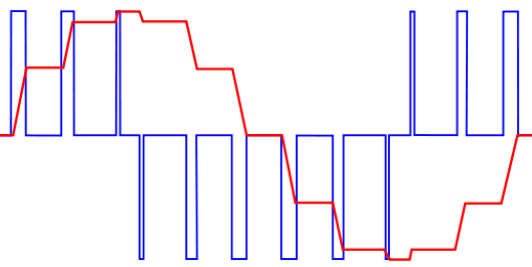
On the other hand, PWM can be explained as the reverse of that. It is a way of controlling analog devices using a digital output. But PWM is not truly an Analog output, however, it pretends to be an Analog like the signal result, by applying power in pulses.
Here is an example to explain it further:
Apply maximum voltage to a motor for a brief amount of time, and then turn it off. Repeat this by changing the time interval between the turning off and turning on. Even though we are applying and removing voltage many times within an interval, it creates a response which is near to being Analog.
How servos are controlled using PWM?
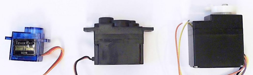
A Servo Motor is a low-speed, high-torque motor and comes in different sizes. These motors are often limited to the following rotation angles: 180, 270 or 90 degrees and are controlled by an electrical signal which determines the amount of movement of the shaft. This signal is a PWM signal and the amount of movement of the shaft is dependent upon the duration of the pulse sent via the control wire.
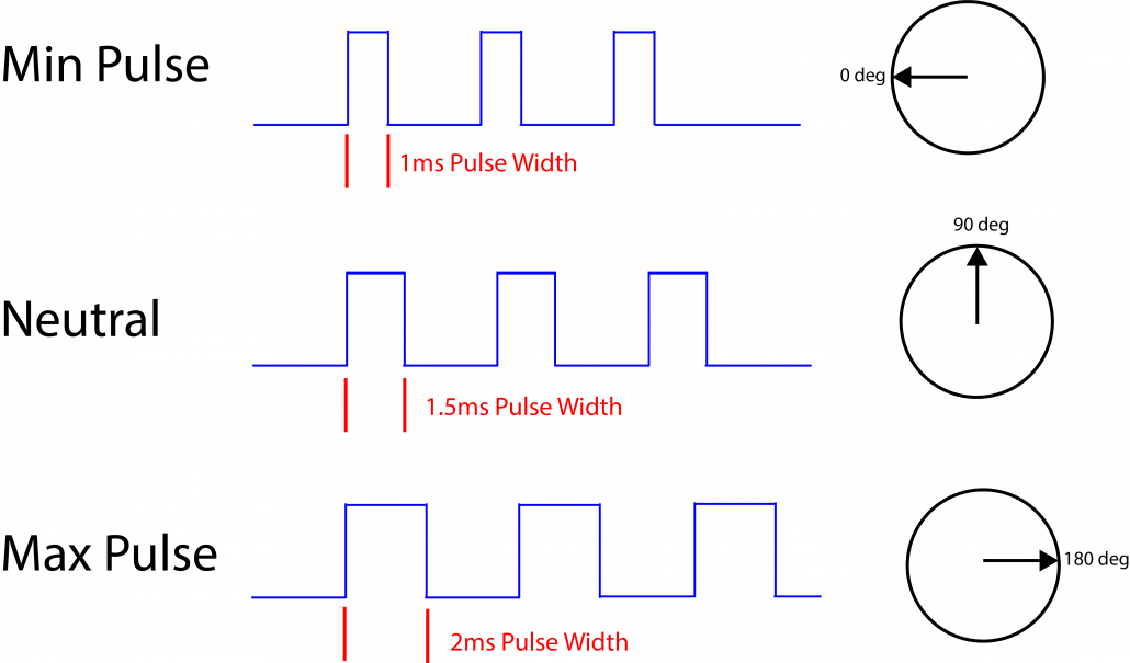
Normally a servo motor expects to see a pulse every 20 milliseconds (ms) and the length of the pulse will determine how far the motor turns. For example, a 1.5ms pulse will make the motor turn to the 90° position. Shorter than 1.5ms moves it in the counterclockwise direction toward the 0° position, and any longer than 1.5ms will turn the servo in a clockwise direction toward the 180° position.
How to test the Grove – 16-Channel PWM Driver (PCA9685) with a single servo motor?
Hardware Needed
- Seeeduino Lotus /Arduino (If Arduino, needs Base Shield)
- Grove – 16-Channel PWM Driver (PCA9685)
- A Servo Motor
Software Setup
- We will be using Arduino IDE to communicate with Seeeduino/ Arduino boards. If you have not already installed Arduino, please do so by visiting the following URL: https://www.arduino.cc/
- Then go to Software > Downloads

- Download the Arduino IDE according to your operating system and Install. Another website will be re-directed, and simply click “Just Download”.

- Install the Arduino IDE following the on-screen installing instructions.
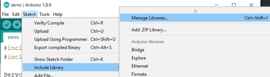
- Open Arduino IDE and go to Sketch > Include Library > Manage Libraries…
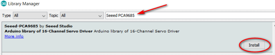
- Type “Seeed PCA9685” in the text box and click install.
Hardware Setup
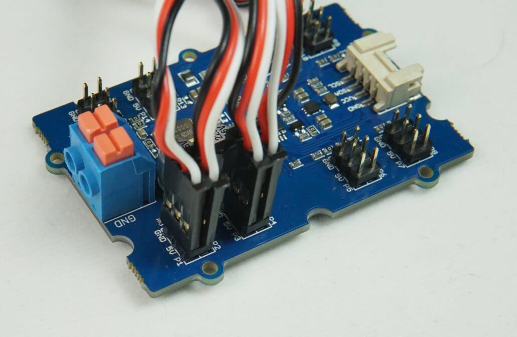
- Connect one end of the Grove cable to Grove – 16-Channel PWM Driver (PCA9685) and the other end to the I2C port of the Seeeduino Lotus/ Base Shield.
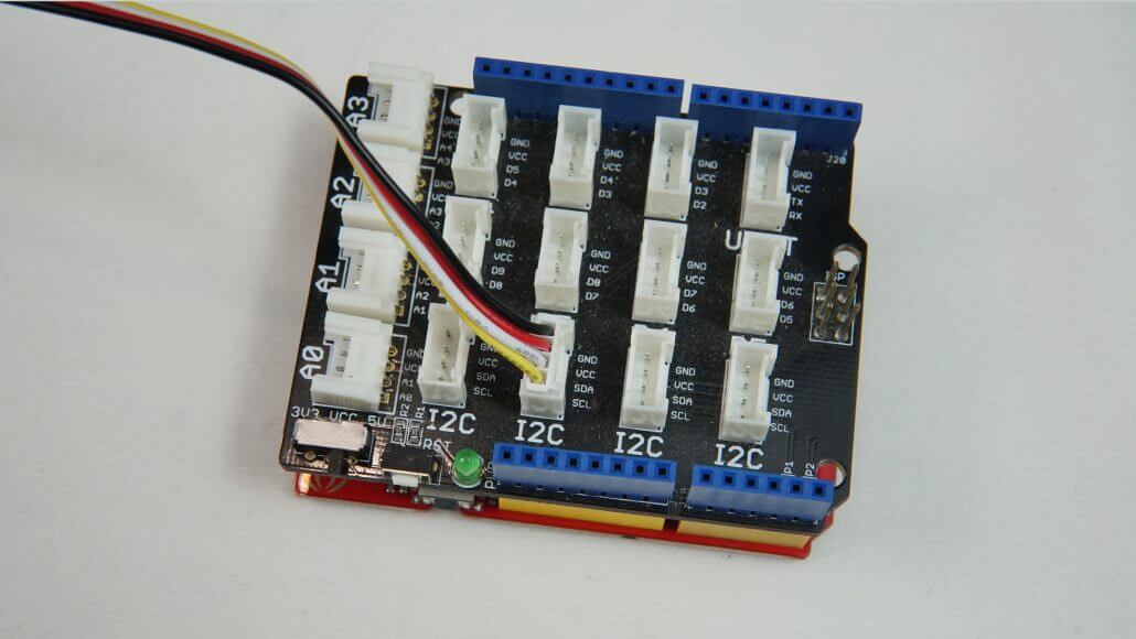
Grove cable connected to I2C port of Base Shield
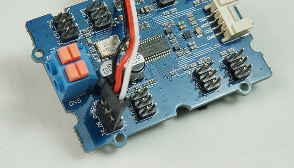
- Then connect a Servo Motor to P1 port of the PWM Driver.
- Insert two wires into the “Power In” port by pushing it down and releasing.
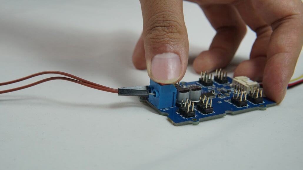
- Provide 5V power through that wire.
- Connect Seeeduino Lotus/ Arduino to power.
Now that everything is set up, jump back to the Arduino IDE and paste the following code inside the IDE.
#include "PCA9685.h"
#include <Wire.h>

ServoDriver servo;

void setup()
{
    // join I2C bus (I2Cdev library doesn't do this automatically)
    Wire.begin();
    Serial.begin(9600);
    servo.init(0x7f);
    // uncomment this line if you need to use a special servo
    // servo.setServoPulseRange(600,2400,180);
}

void loop()
{
  servo.setAngle(1, 0);
  delay(1000);
  servo.setAngle(1, 180);
  delay(1000);

}- Choose the correct board and port by visitng “Tools > Board” and “Tools> Port”.
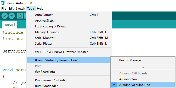
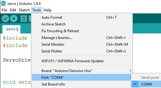
- Then hit the Upload button.

If you followed the setups properly, you will see the servo rotate 180 degrees clockwise and rotates back 180 degrees anti-clockwise.
How to make your own Robotic Arm work with four servos?
Let’s have some more fun with this PWM driver!
Hardware Used
- Seeeduino /Arduino
- Base Shield
- Grove – 16-Channel PWM Driver (PCA9685)
- 4 Servo Motors
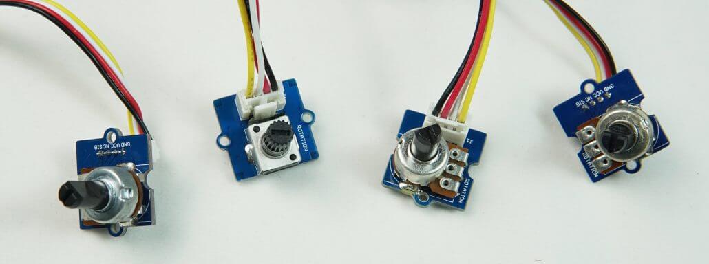
- 4 Grove – Rotary Angle Sensors
- Robotic Arm Frame
Hardware Setup
- Connect Grove – 16-Channel PWM Driver (PCA9685) to the I2C port of the Seeeduino /Base Shield.
- Then connect four servos from port P1 to P4 to the PWM Driver.
- Connect four Grove – Rotary Angle Sensors from ports A0 to A3 to the Base Shield.
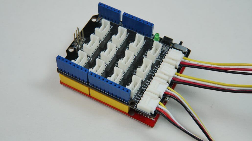
- Insert two wires into the “Power In” port by pushing it down and releasing.
- Provide 5V power through that wire.
- Connect Seeeduino Lotus/ Arduino to power.
Software Setup
- Setup the software as the previous example
- Upload the following code into the Arduino IDE
#include "PCA9685.h"
#include <Wire.h>

ServoDriver servo;
#define RotarySensor_1 A0
#define RotarySensor_2 A1
#define RotarySensor_3 A2
#define RotarySensor_4 A3

void setup()
{
  // join I2C bus (I2Cdev library doesn't do this automatically)
  Wire.begin();
  Serial.begin(9600);
  servo.init(0x7f);
  pinMode(RotarySensor_1, INPUT);
  pinMode(RotarySensor_2, INPUT);
  pinMode(RotarySensor_3, INPUT);
  pinMode(RotarySensor_4, INPUT);

  // uncomment this line if you need to use a special servo
  // servo.setServoPulseRange(600,2400,180);
  Serial.begin(9600);
}
void loop()
{

  int angle[6];
  int sensor_value[6];
  sensor_value[0] = analogRead(RotarySensor_1);
  sensor_value[1] = analogRead(RotarySensor_2);
  sensor_value[2] = analogRead(RotarySensor_3);
  sensor_value[3] = analogRead(RotarySensor_4);

  angle[0] = (float)sensor_value[0] * 300 / 1023;
  angle[1] = (float)sensor_value[1] * 300 / 1023;
  angle[2] = (float)sensor_value[2] * 300 / 1023;
  angle[3] = (float)sensor_value[3] * 300 / 1023;
  Serial.println(angle[0]);

  servo.setAngle(12, map(angle[0], 0, 300, 0, 170));
  servo.setAngle(13, map(angle[1], 0, 300, 0, 180));
  servo.setAngle(14, map(angle[2], 0, 300, 20, 180));
  servo.setAngle(15, map(angle[3], 0, 300, 20, 160));
  //delay(15);


}- Then hit the Upload button as before.
Now you will be able to control your own robotic arm just by rotating the knobs on the Grove – Rotary Angle Sensors!!
Summary
And that’s all on using Grove – 16-Channel PWM Driver (PCA9685) to Control Robotic Arm! Did you learn something new? We hope this post has helped you learn more about PWM drivers, and do stay tuned for more content coming up in the future!