Getting Started with NRF24L01 Transceiver: Arduino Guide
NRF24L01+, a popular 2.4GHz RF wireless Transceiver Module among Arduino Users. Regarded highly for its cost to performance ratio, it features specs that’s one of the best in its league. This blog aims to explain what it’s capable of, alongside an NRF24L01 Arduino Guide.
What’s good about the nRF24l01?
When it comes down to cheap yet reliable 2-way RF solutions, there isn’t any module that does a better job than the nRF24L01. Here’s why:
Low cost – The NRF24L01 is one of the cheapest wireless transceiver modules in the market, you can easily grab one online for less than USD2!
Ease of Pairing with Microcontroller/Arduino Board – The nRF24L01 can be easily paired with a variety of microcontroller systems; MCU/ARM/PIC/AVR/STM32 by using the SPI protocol or an RF24 library when pairing with Arduino.
2.4Ghz for wireless communication flexibility – 2.4GHz operating frequency allows for higher bit rate usages rather than other lower operating frequencies. It uses GFSK modulation for data transmission as well, meaning data transfer rate can either be 250kbps, 1Mbps or 2Mbps.
High transmission range – The nRF24L01, when used with the right setup, is able to transmit wavelengths over several kilometres. However, if you need a standalone module with a high transmission range, you can check this nRF24L01+ module that’s designed with a power amplifier and IPX antenna for wireless communication of up to 1000 meters (no barrier)
Endless Applications – Ranging from Wireless PC Peripherals to controllers and toys, the nRF24L01 is applicable to be used for many scenarios.
Here’s a non-exhaustive list of applications:
- Wireless PC Peripherals
- Mouse, keyboards, and remotes
- 3-in-1 desktop bundles
- Advanced Media centre remote controls
- VoIP headsets
- Game controllers
- Sports watches and sensors
- RF remote controls for consumer electronics
- Home and commercial automation
- Active RFID
- Asset tracking systems
- Toys
What about the NRF24L01+?
You may have stumbled upon that some of the NRF24L01 on the market consist of “+” and wonder what’s the difference between the normal version and the + version.
Here’s the difference:
The NRF24L01+ is a newer version of the NRF24L01, capable of doing an extra 250kbps of on-air data rate while the one without “+” has only 1Mbps and 2Mbps.
Apart from that, they can both be considered as identical to one another
Both versions can be mixed together as long as 1 or 2 MBps is being used as the data rate.
nRF24L01+ module vs nRF24L01+ PA Module
There are a variety of modules available that are based on the nRF24L01+ chip, here are the popular ones that are worth taking a look at:
First Version:
The above wireless module comes with an onboard antenna. Its small and compact size may be suitable for compact spaces but loses out in transmission range, limiting on module applications.
Second Version:

This version comes with an external IPX antenna and is designed with a power amplifier. This allows for a way wider transmission range of up to 1000 meters. Hence, achieving a good balance between wireless transmission performance and cost.
Here at Seeed, we carry the second version of the NRF24L01 module that can be purchased at our online store!
NRF24L01 Arduino Guide
In this guide, we’ll be using the first version of NRF2401 that comes with the onboard antenna instead.
It’ll be kept simple by using a regular cherry switch, where when clicked, it’ll send a value that’s picked up by another module and light up a WS2812 LED stick.
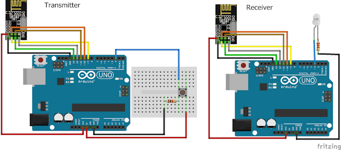
Transmitter + Receiver Connections:
Board used: Arduino Nano
- Consider Seeeduino Nano, a better alternative
Switch and Nano configuration:
The switch is connected to the GND and Pin 8 on the Nano
Nano and NRF24L01 pin configuration:
- MISO connects to pin 12 of the Nano
- MOSI connects to pin 11 of the Nano
- SCK connects to pin 13 of the Nano
- CE connects to pin 9 of the Nano
- CSN connects to pin 10 of the Nano
- GND and VCC of the NRF24L01 are connected to GND and 3.3V of the Nano
It’s recommended to use Arduino Nano and Uno as they share the same SPI pins.
Transmitter Code:
Copy the sketch code below in your Arduino IDE software to program your Arduino
/*
Created by Yvan / https://Brainy-Bits.com

This code is in the public domain...
You can: copy it, use it, modify it, share it or just plain ignore it!
Thx!

*/

// NRF24L01 Module Tutorial - Code for Transmitter using Arduino NANO

//Include needed Libraries at beginning
#include "nRF24L01.h" //NRF24L01 library created by TMRh20 https://github.com/TMRh20/RF24
#include "RF24.h"
#include "SPI.h"

#define SwitchPin 8 // Arcade switch is connected to Pin 8 on NANO
int SentMessage[1] = {000}; // Used to store value before being sent through the NRF24L01

RF24 radio(9,10); // NRF24L01 used SPI pins + Pin 9 and 10 on the NANO

const uint64_t pipe = 0xE6E6E6E6E6E6; // Needs to be the same for communicating between 2 NRF24L01


void setup(void){

pinMode(SwitchPin, INPUT_PULLUP); // Define the arcade switch NANO pin as an Input using Internal Pullups
digitalWrite(SwitchPin,HIGH); // Set Pin to HIGH at beginning

radio.begin(); // Start the NRF24L01
radio.openWritingPipe(pipe); // Get NRF24L01 ready to transmit
}

void loop(void){

if (digitalRead(SwitchPin) == LOW){ // If Switch is Activated
SentMessage[0] = 111;
radio.write(SentMessage, 1); // Send value through NRF24L01
}
else {
SentMessage[0] = 000;
radio.write(SentMessage, 1);
}
}
Board used: Arduino Uno
The receiver part will be the one that has the WS2812 LED stick, receiving information sent by the Transmitter.
WS2812 LED and Uno Pin Configuration:
- DI pin on the WS2812 is connected to Pin 8 on the Uno
- GND and VCC on the WS2812 are connected to the GND and 5V of the Uno
NRF24L01 and Uno Pin Configuration:
- MISO connects to pin 12 of the Uno
- MOSI connects to pin 11 of the Uno
- SCK connects to pin 13 of the Uno
- CE connects to pin 9 of the Uno
- CSN connects to pin 10 of the Uno
- GND and VCC are connected to GND and 3.3V of the Uno
Receiver Code:
Copy the sketch code below in your Arduino IDE software to program your Arduino
/*
Created by Yvan / https://Brainy-Bits.com

This code is in the public domain...
You can: copy it, use it, modify it, share it or just plain ignore it!
Thx!

*/


// NRF24L01 Module Tutorial - Code for Receiver using Arduino UNO

//Include needed Libraries at beginning
#include "nRF24L01.h" // NRF24L01 library created by TMRh20 https://github.com/TMRh20/RF24
#include "RF24.h"
#include "SPI.h"
#include "FastLED.h" // FastLED library for WS2812 RGB Stick http://fastled.io/

#define NUM_LEDS 8 // Number of leds on stick
#define LED_PIN 8 // Digital In (DI) of RGB Stick connected to pin 8 of the UNO

CRGB leds[NUM_LEDS]; // FastLED Library Init

int ReceivedMessage[1] = {000}; // Used to store value received by the NRF24L01

RF24 radio(9,10); // NRF24L01 used SPI pins + Pin 9 and 10 on the UNO

const uint64_t pipe = 0xE6E6E6E6E6E6; // Needs to be the same for communicating between 2 NRF24L01


void setup(void){

FastLED.addLeds<NEOPIXEL,LED_PIN>(leds, NUM_LEDS); // Setup FastLED Library
FastLED.clear(); // Clear the RGB Stick LEDs

// Light up starting LED's
for(int x = 0; x != NUM_LEDS; x++) {
leds[x] = CRGB::Red;
}

FastLED.setBrightness(50);
FastLED.show();

radio.begin(); // Start the NRF24L01

radio.openReadingPipe(1,pipe); // Get NRF24L01 ready to receive

radio.startListening(); // Listen to see if information received

pinMode(LED_PIN, OUTPUT); // Set RGB Stick UNO pin to an OUTPUT
}

void loop(void){

while (radio.available())
{
radio.read(ReceivedMessage, 1); // Read information from the NRF24L01

if (ReceivedMessage[0] == 111) // Indicates switch is pressed
{
for(int x = 0; x != NUM_LEDS; x++)
{
leds[x] = CRGB::Green;
FastLED.show();
}
}
else
{
for(int x = 0; x != NUM_LEDS; x++)
{
leds[x] = CRGB::Red;
FastLED.show();
}
}
delay(10);
}
}
For the full tutorial, you can head here!
Summary
Overall, the nRF24L01 is a great option if you’re looking to set up your wireless communication system at a low cost. Its high cost to performance ratio and ease of pairing with your microcontroller systems makes it the popular option than it already is.
The 2nd version of the NRF24L01+ is highly recommended for that boost in wireless communication performance if that’s what you’re looking for.