How to use an MPU9250 Accelerometer and Gyroscope With Arduino
Ever heard of MPU-9250? It is a multi-chip module (MCM) which consists of 2 dies, and houses the 3-Axis gyroscope and the 3-Axis accelerometer! Still unsure about how it works? Read on to find out! Hope that this article will help you understand the applications of MPU9250 and how to interface it with Arduino!
In today’s tutorial, we will be learning how to use an MPU9250 Accelerometer and Gyroscope with the Arduino. This tutorial will cover:
- How does the MPU9250 Accelerometer and Gyroscope work?
- About the MPU9250 IMU (Inertial Measurement Unit)
- Tutorial on how to use an MPU9250 Accelerometer and Gyroscope With Arduino
- Applications of the IMU
How does the MPU9250 Accelerometer and Gyroscope work?
There are accelerometer and gyroscope sensors on their own which are used to measure acceleration and rotational changes respectively. As shown below:


But in this tutorial, we will be using an MPU9250 IMU which has both 3-Axis accelerometer and 3-Axis gyroscope integrated on a single chip. In addition, it also has a magnetometer integrated which serves as the tool for gravitational force measurement.

Accelerometer Working Principle
An Accelerometer measures the rate of change of velocity of an object with respect to time also known as acceleration. With an accelerometer, you are able to figure out the angle the sensor is tilted at with respect to the ground.
An accelerometer has microscopic crystals that go under stress when vibrations occur. From that stress, a voltage is generated which creates a reading on any acceleration. The unit of measurement for acceleration is meter per second squared (m/s^2). But as accelerometer sensors express measurements in “g”, one “g” is the value of the earth gravitational force which is equal to 9.8 meters per second squared.
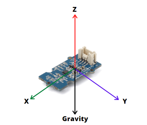
For example, in a 3 axis accelerometer like the MPU9250 Accelerometer sensor, when placed flat with the Z-axis pointing up, Z-axis output of sensor = 1 g or 9.8m/s^2 while X and Y = 0. This is due to the gravitational force being perpendicular to these axes which do not affect them.
From this data, the sensor is able to use simple trigonometry math and calculate the angle of the sensor.
Gyroscope Working Principle
The Gyroscope which measures rotational velocity/rate of change of angular position over time works through the Coriolis effect and MEMS technology.
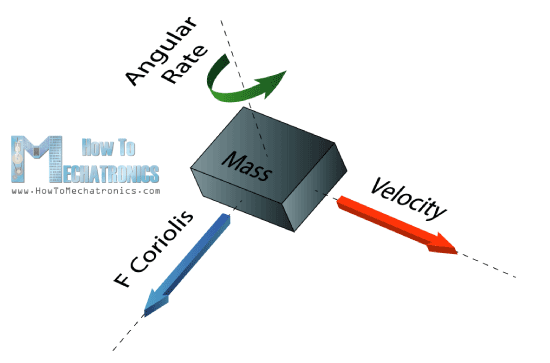
When a mass is moving in a particular direction with a particular velocity and when an external angular rate will be applied as shown with the green arrow a force will occur which the sensor will detect.
As shown above, labelled by the blue and red arrow, this will cause perpendicular displacement of the mass. The displacement will cause a change in capacitance which will be measured, processed and it will correspond to a particular angular rate.
The outputs of the gyroscope are in degrees per second, so in order to get the angular position, we just need to integrate the angular velocity.
For a full explanation of how a Gyroscope works, you can check out Elprocus page here.
About the MPU9250 IMU (Inertial Measurement Unit)
IMU which stands for Inertial Measurement Unit is defined as a 9-axis sensor that measures orientation, velocity, and gravitational forces by combining Accelerometer, Gyroscope, and Magnetometer into one. IMUs typically come in large packages, but with recent developments like MEMS technology, they are now more commonly seen as miniaturized sensors designed for easy integration with Arduino or other microcontrollers.
In today’s tutorial, we will be using an IMU that is a 9-axis motion tracking module based on MPU-9250.
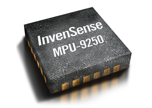
The MPU-9250 is a 9-axis MEMS sensor from InvenSense®. The MPU-9250 features:
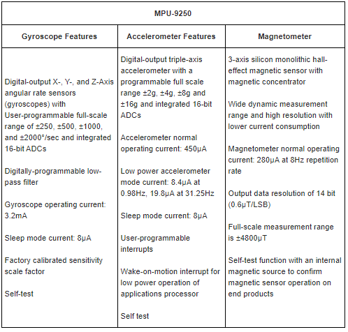
Additional Features of the MPU9250 includes:
- Smallest and thinnest QFN package for portable devices: 3x3x1mm
- Auxiliary master I2C bus for reading data from external sensors
- Minimal cross-axis sensitivity between the accelerometer, gyroscope and magnetometer axes
- 512 byte FIFO buffer enables the applications processor to read the data in bursts
- Digital-output temperature sensor
- 10,000 g shock tolerant
- 400kHz Fast Mode I2C for communicating with all registers
- Serial interfaces:
- 1MHz for communicating with all registers
- 200MHz for reading sensor and interrupt registers

This IMU based on MPU-9250 is not only affordable, but it also requires low power while offering high performance.
The Grove – IMU 9DOF v2.0 – MPU-9250 also features a user-programmable gyroscope full-scale range of ±250, ±500, ±1000, and ±2000°/sec (DPS), a user-programmable accelerometer full-scale range of ±2g, ±4g, ±8g, and ±16g, and a magnetometer full-scale range of ±4800µT.
In the industrial fields, Grove – IMU 9DOF v2.0 – MPU-9250 includes programmable digital filters, a precision clock with a 1% drift from -40°C to 85°C, an embedded temperature sensor, and programmable interrupts. Grove – IMU 9DOF v2.0 – MPU-9250 features I2C, SPI serial, and plug and play Grove interfaces.
Tutorial on how to use an MPU9250 Accelerometer and Gyroscope With Arduino
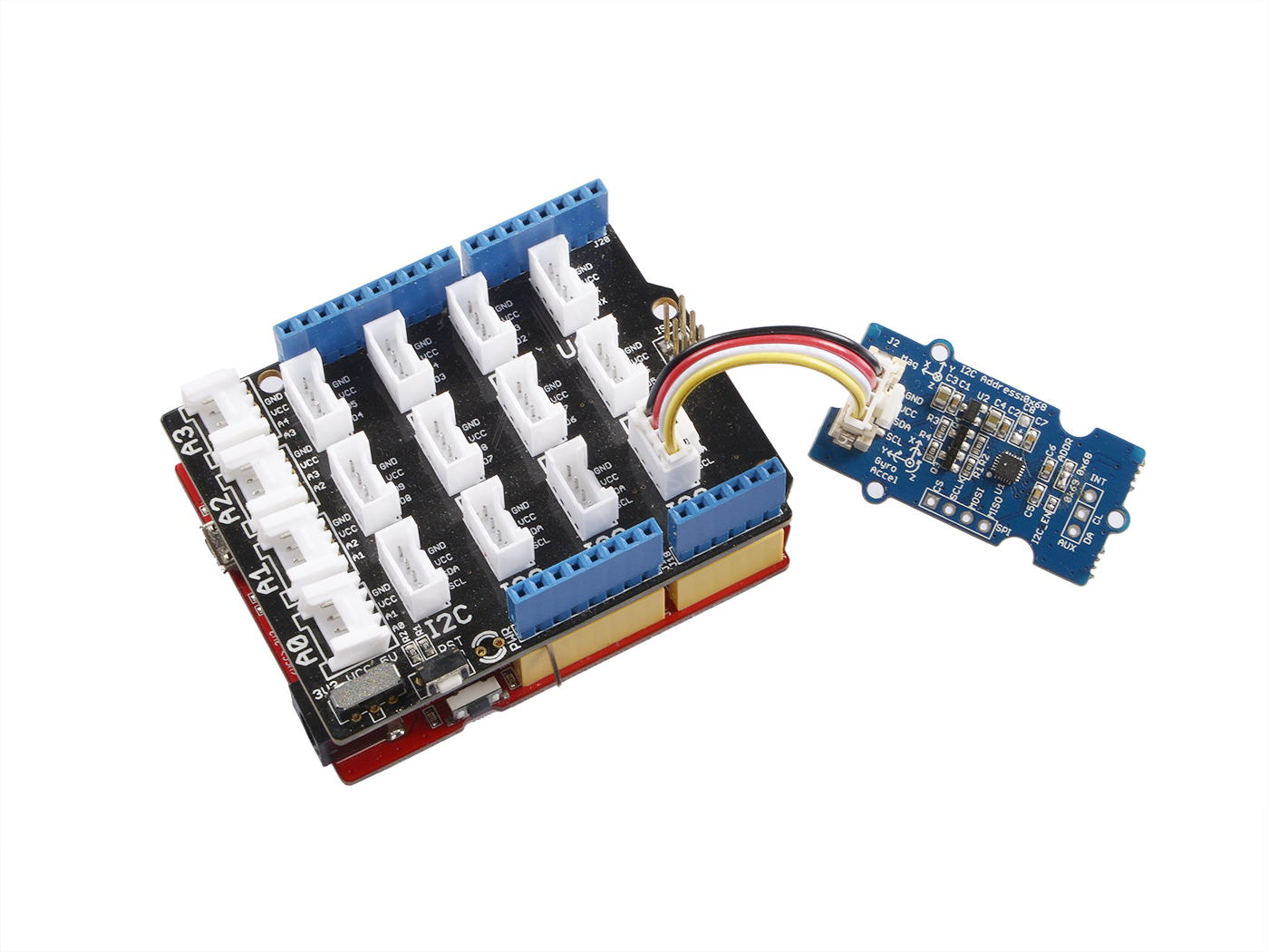
Let’s jump into how can we connect the MPU9250 IMU sensor to the Arduino. As the sensor module we are using is part of our Grove collection, connecting the sensor to the Arduino is much easier and faster.
What you’ll need:
- Arduino UNO / Seeeduino V4.2 (Seeed’s very own Arduino)
- Grove – Base Shield (Optional, to make connection easier)
- Grove – IMU 9DOF v2.0
Step by Step Instructions
Hardware
Step 1 – Connect Grove-IMU_9DOF_v2.0 to port I2C of Grove-Base Shield.
If you do not have a Grove Base Shield, you can directly connect the IMU module to your Arduino following the table below:
| Arduino | Grove – IMU 9DOF v2.0 |
| 5V | VCC |
| GND | GND |
| SDA | SDA |
| SCL | SCL |
Step 2 – Plug Grove – Base Shield into Seeeduino.
Step 4 – Connect Seeeduino to PC via a USB cable. Your connection should look something like this:
Software
Step 1 – Download the IMU library from Github.
If you do not know how to install library on Arduino IDE, you can refer to this guide on How to install library for Arduino
Step 2 – Create a new Arduino sketch and paste the codes below to it or open the code directly by the path:
File -> Example ->IMU_9DOF_Demo_Compass_Calibrated->IMU_9DOF_Demo_Compass_Calibrated.
Here is the main code:
void setup() {
// join I2C bus (I2Cdev library doesn't do this automatically)
Wire.begin();
// initialize serial communication
// (38400 chosen because it works as well at 8MHz as it does at 16MHz, but
// it's really up to you depending on your project)
Serial.begin(38400);
// initialize device
Serial.println("Initializing I2C devices...");
accelgyro.initialize();
// verify connection
Serial.println("Testing device connections...");
Serial.println(accelgyro.testConnection() ? "MPU9250 connection successful" : "MPU9250 connection failed");
delay(1000);
Serial.println(" ");
//Mxyz_init_calibrated ();
}
void loop()
{
getAccel_Data();
getGyro_Data();
getCompassDate_calibrated(); // compass data has been calibrated here
getHeading(); //before we use this function we should run 'getCompassDate_calibrated()' frist, so that we can get calibrated data ,then we can get correct angle .
getTiltHeading();
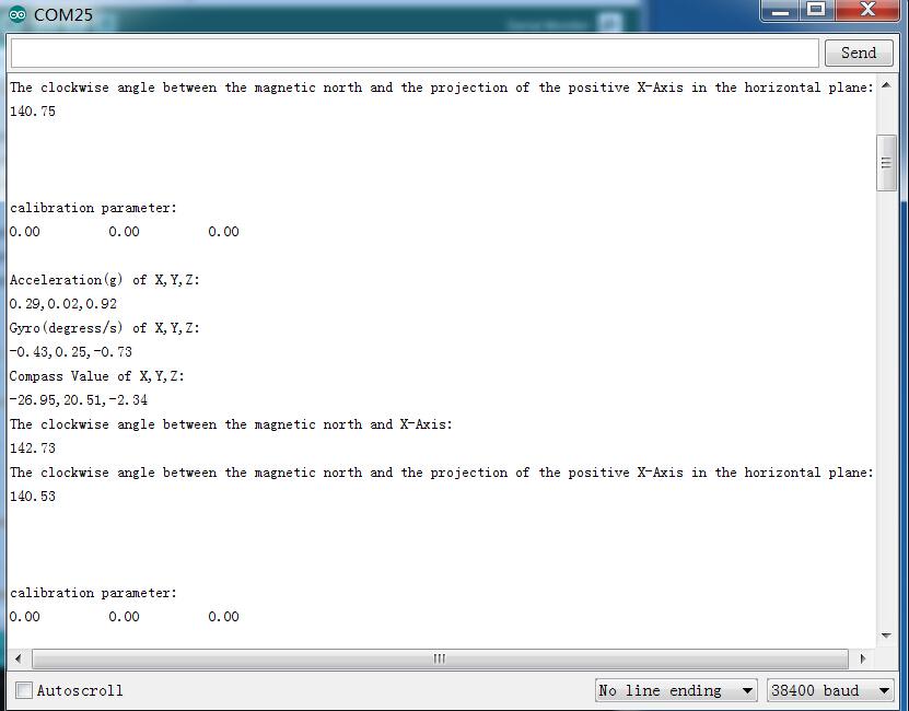
Serial.println("calibration parameter: ");
Serial.print(mx_centre);
Serial.print(" ");
Serial.print(my_centre);
Serial.print(" ");
Serial.println(mz_centre);
Serial.println(" ");
Serial.println("Acceleration(g) of X,Y,Z:");
Serial.print(Axyz[0]);
Serial.print(",");
Serial.print(Axyz[1]);
Serial.print(",");
Serial.println(Axyz[2]);
Serial.println("Gyro(degress/s) of X,Y,Z:");
Serial.print(Gxyz[0]);
Serial.print(",");
Serial.print(Gxyz[1]);
Serial.print(",");
Serial.println(Gxyz[2]);
Serial.println("Compass Value of X,Y,Z:");
Serial.print(Mxyz[0]);
Serial.print(",");
Serial.print(Mxyz[1]);
Serial.print(",");
Serial.println(Mxyz[2]);
Serial.println("The clockwise angle between the magnetic north and X-Axis:");
Serial.print(heading);
Serial.println(" ");
Serial.println("The clockwise angle between the magnetic north and the projection of the positive X-Axis in the horizontal plane:");
Serial.println(tiltheading);
Serial.println(" ");
Serial.println(" ");
Serial.println(" ");
delay(300);
}Step 3 – After uploading the code, you should see the results appear. It should look something like this:
References
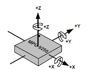
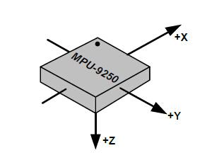
To help you out, here’s a diagram that shows the orientation of the axes of sensitivity and the polarity of rotation.
Applications of the MPU9250 Accelerator and Gyroscope
Now that you know how the MPU9250 IMU works, here are some projects and applications you can do with it:
- Consumer electronics; Smartphones, tablets, fitness trackers for motion sensing and orientation
- GPS and satellite positioning systems
- Sports technology and training applications
- Personal transportation devices like Segway for stabilization/balancing of the vehicle
- Inertial Navigations Systems to control aircraft, ships, submarines, and other unmanned aerial vehicles
- Anywhere that needs motion detection
Summary
That’s all for today’s tutorial on how to use an MPU9250 Accelerometer and Gyroscope with the Arduino.
For more information on the MPU9250, you can check out its datasheet and register map.
If you have any questions regarding this tutorial please leave a comment down below!
Looking for a much more efficient IMU? We got one for you! It is the Grove – IMU 10DOF v2.0. Based on the newly released BMP280, this IMU sensor module is only 65% smaller than the BMP180, but consumes way lesser power; only 2.7uA@1Hz!