Voltage Dividers – Circuits, Equation and Applications
The voltage divider also known as the Potential Divider, is a very common simple circuit which is used to change a large voltage into a small voltage. Through this article, you will learn about:
- What is a Voltage Divider?
- Voltage Divider Circuits
- Voltage Divider Equation / Formula
- Applications of Voltage Dividers
What is a Voltage Divider?
- Passive Linear Circuit that produces output voltage that is a fraction of its input voltage.
- It scales down input voltage to a smaller voltage based on the ratio of the 2 resistors through distributing input voltage among components of the divider.
- Often used to supply a voltage different from an available battery or power supply.
- Output voltage of voltage divider is dependent on the resistance of the incoming load.
Voltage Divider Circuit
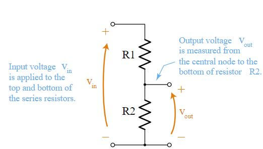
A voltage divider circuit will normally look like this in a circuit with a series of 2 resistors.
- R1 = Resistor closest to input voltage (Vin)
- R2 = Resistor closest to ground
- Vin= Input Voltage
- Vout = Output voltage across R2 which is the divided voltage (1/4 of input voltage)
Voltage Divider Formula / Equation
Equation to find the output voltage of a Divider Circuit:
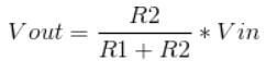
R2 / R1 + R2 = Ratio determines scale factor of scaled down voltage.
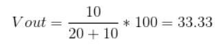
For example,
Vin = 100, R1= 20, R2= 10
With the help of a calculator you should get:
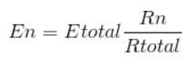
Voltage Divider Rule
- The voltage division rule states that: The voltage divided between two series resistors, are in direct proportion to their resistance
- Which means your circuit can have more than 2 resistors!
- Voltage Divider Rule Formula:
Example of Voltage Divider Rule Equation:
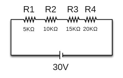
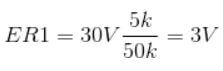
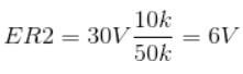
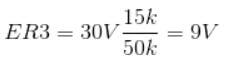
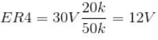
Ohm’s Law
Now, we can use Ohm’s Law to calculate the voltage flowing through each resistor:
- Equation for Ohm’s Law = E = IR
- E = Current across each resistor
- I = Circuit Current
- R = Resistance
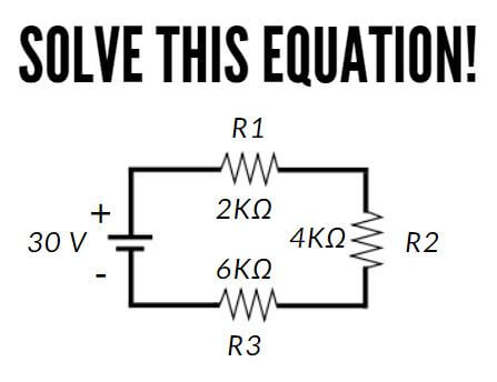
| R1 | R2 | R3 | Total | |
| E (Volts) | 5 | 10 | 15 | 30 |
| I (Amps) | 2.5m | 2.5 | 2.5m | 2.5m |
| R (Ohms) | 2K | 4K | 6K | 12K |
Thus, the current across each resistor is 5V, 10V and 15V respectively!
Simplified Equations
- If R1 = R2,
- If you are solving for R1,
- If you are solving for R2,
Applications of Voltage Dividers
Voltage dividers circuits are very common and are found in many applications. Here are a few examples of where a Voltage Divider circuit is found:
Potentiometer
- A potentiometer is passive electronic component with a sliding or rotating function that acts as an adjustable voltage divider.
- The voltage input is applied across the entire length of the Potentiometer and output voltage (voltage drop) is controlled with the fixed and sliding contact of the potentiometer.
- There are two types of Potentiometer
- Rotary Potentiometers (Rotary Knob)
- Linear Potentiometer (Slider)
- Here at Seeed, we offer both types!
Grove – Slide Potentiometer
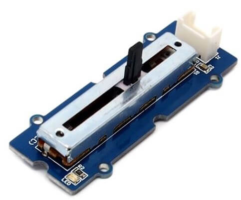
- How does it work?
- The manual wiper which is movable, touches a resistive strip of material. When it is moved up closer to terminal 1 and away from terminal 2, resistance is lowered to terminal 1 while resistance is raised at terminal 2 and vice versa.
- The potentiometer is useful to help achieve a variable voltage from a fixed-voltage source. It can connect the outer terminals of a potentiometer across the voltage source and control the voltage you need between your potentiometer and one of the outer terminals for your circuit.
- The Grove – Slide Potentiometer incorporates a linear variable resistor with a maximum resistance of 10KΩ. As the slider moves, the output voltage will range from 0 V to the Vcc you apply.
- It connects to other Grove modules through a standard 4-pin Grove Cable.
- Below is an image of the Potentiometer schematic diagram:
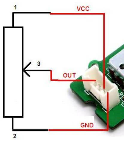
- It has many purposes like being an Adjustable Resistor, standalone, voltage divider with Arduino or even as a human interface device (HID) which means it can be used to control a car!
- Some projects you can do with the Grove – Slide Potentiometer are like making your very own Beatbox or Boombox with Arduino!
Grove – Rotary Angle Sensor(P)
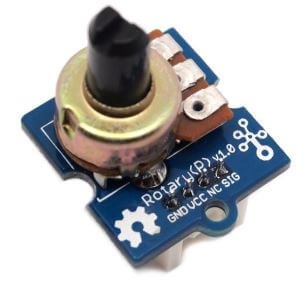
- The Grove-Rotary Angle Sensor (P) is capable of producing analog output between 0 and Vcc (5V DC with Seeeduino) on its D1 connector.
- With a resistance value at 10k Ohms, it is perfect for Arduino use.
- It is supported on all MCU platforms like Arduino, Raspberry Pi, BeagleBone, Wio and also LinkIt ONE.
- One of the projects that you can do with this potentiometer is using it to control your LEDs brightness
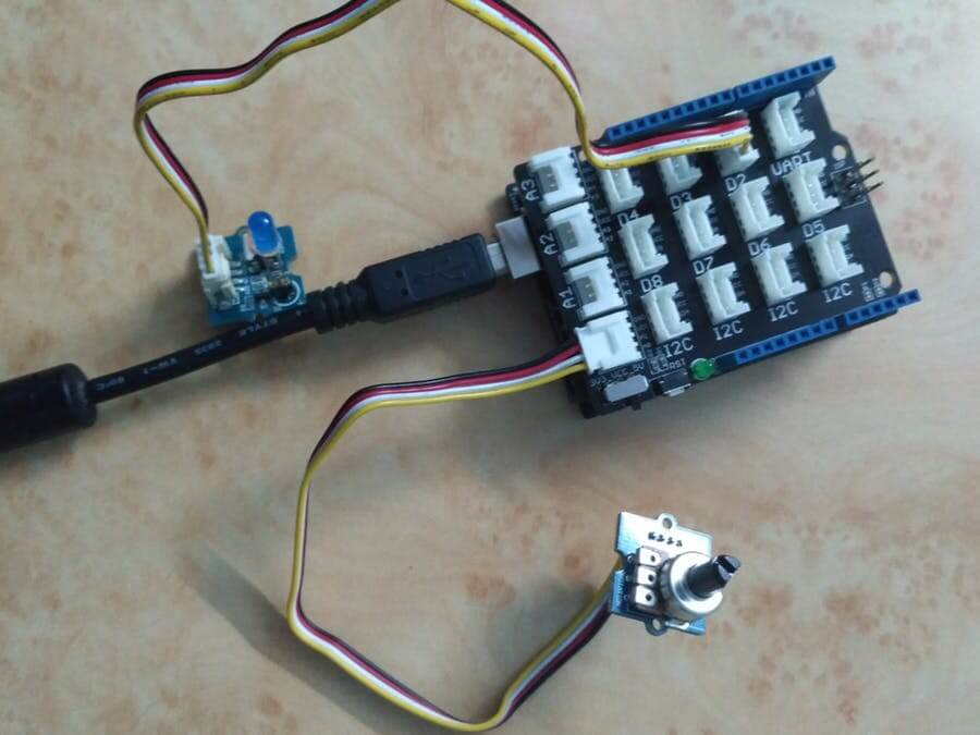
- Interested? You can check out the projects ideas here and also for more detailed information on our wiki page: Grove – Rotary Angle Sensor Wiki
- Want to know more about Potentiometer Functions, types, etc? Check out our other blog about Potentiometer – Functions, Types and Applications!
Grove – Voltage Divider
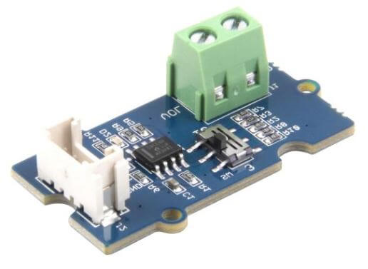
- The Grove – Voltage Divider provides an interface for measuring external voltage which eliminates the need to connect a resistance to input interface
- With a dial switch, you can easily select the voltage gain which makes it simple to use.
Resistive Sensors Reading
- Most sensors are simple resistive devices like our Grove – Infrared Reflective Sensor. However, most of them are only able to read voltage but not resistance.
- By adding another resistor to the circuit, we are able to create a voltage divider together with the sensor.
- As we are able to check the output of the voltage divider, we can now calculate the amount of resistance of the sensor.
- An example of the circuit is as shown below where R2 is a resistive sensor:
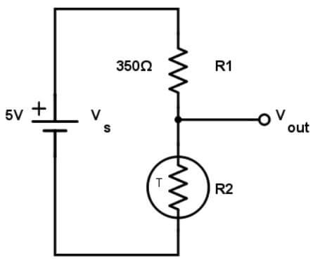
- For example, the resistive sensor is a Grove – Temperature Sensor which is a thermistor with a room temperature resistance of 350 Ω where the resistance of R1 is fixed at 350 Ω
- Using the Voltage Divider Equation:
| Temperature | Vin (Fixed) | R2 | R1 | R2 / (R1+R2) | Vout |
|---|---|---|---|---|---|
| Cold | 5V | 300 Ω | 350 Ω | 0.46 | 2.3V |
| Room Temperature | 5V | 350 Ω | 350 Ω | 0.5 | 2.5V |
| Hot | 5V | 400 Ω | 350 Ω | 0.53 | 2.65V |
Level Shifters
- What happens when a sensor and a microcontroller with two different voltage meets? Without the voltage leveled down, for example, directly interfacing a 5V logic output microcontroller to a 3.3V input sensor can cause damage to your 3.3V circuit.
- This is where the hero: A voltage divider comes in and saves the day acting as a level shifter which interfaces two circuits that use different operating voltages.
- The voltage divider can help level the voltage down from a microcontroller (eg. 5V to 3.3V) to avoid damage to the sensor which makes it safe for the sensor to handle.
- Do take note that the voltage divider can only work in one direction: level down voltages but not leveling up.
- Here is a table of resistor combinations for leveling down commonly encountered voltages:
| Resistor Combination | Voltages to be leveled down |
|---|---|
| 4.7 kΩ and 3.9 kΩ | 9V to 5V |
| 3.6 kΩ and 9.1 kΩ | 12V to 3.3V |
| 3.3 kΩ and 5.7 kΩ | 9V to 3.3V |
- Do note that it is not recommended using a voltage divider to level down a large load like 12V to 5V as they are not meant to supply such power to a load as with such a load, it may melt the resistor. (You can use voltage regulators instead like our Adjustable DC&DC Power Converter (1.25V – 35V&3A)
Summary
With all the knowledge of Voltage Divider in your hands, you are able to turn any voltage into a smaller one like a magician! Want to test your skills by making your very own Voltage Divider project? Here are some project ideas to get you started using a potentiometer and an Arduino to create a beatbox or a boombox on our wiki page: Grove – Slide Potentiometer Wiki
The formula is WRONG
The formula should be Vout = Vin x (R2/(R1 + R2))
Looking at your example:
100 * (10/(10+20)) = 33.33 NOT 66.67 as you indicate.
Doesn’t anyone check this stuff before you post it?
Hi Frank,
I’m sorry for such a mistake. We try to make sure the content that we post are all correct and reliable. In this case, we clearly fell short. We have already corrected the mistake!
Once again, sorry for the inconvenience caused and thank you for letting us know. Your feedback is valuable to us.