Getting Started with Arduino Motors – DC, Stepper, Servo Motor
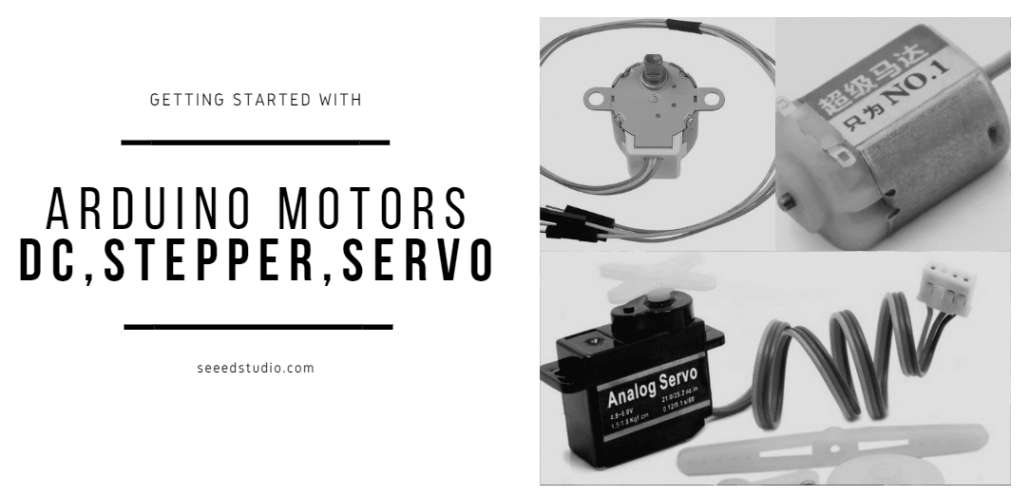
When using the Arduino, there are many projects and things that you can do with it and one of them includes driving a motor! Today, through this tutorial, we will be focusing on the 3 basic motors that you can drive with the Arduino which are the DC motor, Servo motor, and Stepper motor.
Today’s guide will cover:
- Introduction to DC, Servo and Stepper Motor
- When to use each motor?
- Getting Started with Seeed’s Arduino Motor Pack
- Arduino DC Motor Tutorial
- Arduino Servo Motor Tutorial
- Arduino Stepper Motor Tutorial
Introduction to DC, Servo and Stepper Motor
DC Motor
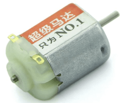
What is the DC Motor?
DC Motor refers to a rotating electrical machine that can convert direct current electrical energy into mechanical energy. It is a motor that can convert electrical energy into mechanical energy in order to run. Correspondingly, the motor that uses AC power is an AC motor.
DC Motor consists of:
- Stator
- Rotor
The static part of the DC motor is called the stator, and its main function is to generate a magnetic field. The part that rotates during operation is called the rotor, and its main function is to generate electromagnetic torque and induced electromotive force, usually also called the armature.
Why can the DC motor rotate?
That’s because of the left-hand rule. When the current flows through the rotor, the rotor generates force in the magnetic field, which can rotate.When current is passed through, the opposite polarity between the two magnetic fields inside the motor causes it to spin continuously in one direction until the current stops.
DC motors have no polarity (Unless marked with + or -), which means you can reverse the direction of the motor by swapping the two wires.
Basically, when a DC motor two leads (positive and negative) are connected directly to a power source, the motor will rotate and in a direction. When the leads are switched, the motor will rotate in the opposite direction.
Advantages of DC motor
- Smooth speed regulation
When the load is unchanged, by changing the voltage across the DC motor, the speed can be easily adjusted in a wide range.
- High starting torque
With DC motors high starting torque, they are very suitable for driving heavy loads in starting conditions. An example of DC motors application would be in electric trains and cranes.
- Do not have harmonics
Compared with other harmonic motors, DC motors are more efficient, more energy-saving, and have a longer service life.
Disadvantages of DC motor
- Not suitable for use in explosive or hazardous conditions, because the brush may generate sparks, which may cause commutation failure.
- Due to the existence of the commutator and brush gear, operation and maintenance costs are increased.
Servo Motor
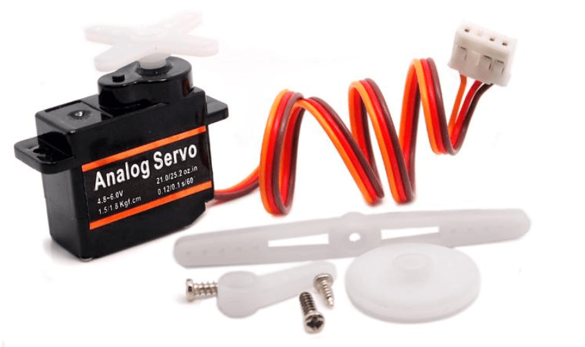
What is the Servo Motor?
The Servo motor is a rotary actuator that allows for precise control of angular position which makes them suitable for use in closed-loop systems where precise position control is needed and is commonly used in electronics.
Servo motors are part of a closed-loop system and they are a self-contained electrical device that rotates parts of a machine with high efficiency with great precision.
Servo Motors are made up of:
- Control Circuit
- Small DC Motor
- Potentiometer
The working principle of servo motor
They are attached by gears to the control wheel where when the motor rotates, the potentiometer resistance changes so the control circuit can precisely regulate how much movement there is and in which direction.
The motor is controlled with an electric signal, either analog or digital, which determines the amount of movement which represents the final command position for the shaft.
With its closed-loop mechanism, it incorporates positional feedback to control the rotational or linear speed and position. A variety of angles are set upon, and there is a notation for an angle of operation of 120 degrees.
Advantages of Servo motor
- High output power relative to motor size and weight
- High efficiency
- Can approach 90% at light loads
- Feedback for controlling the speed and torque.
- The encoder determines accuracy and resolution.
- Encoder Utilization provides higher accuracy and resolution with closed-loop control.
- High Torque to inertia ratio
- Servo Motors can rapidly accelerate loads.
- Resonance and vibration-free operation
- High-speed operation is possible
- Servo motors can achieve high speed at high torque values
Disadvantages of Servo motor
- Requires tuning to stabilize the feedback loop.
- Servo motors are unpredictable when something is broken
- Thus, safety circuits are required.
- Complex controller requires encoder and electronic support.
- Servo Motor can be damaged by sustained overload
- Peak torque is limited to a 1% duty cycle
- Cost can be higher than that of stepper motor
- The requirement for feedback components can increase the overall system cost and installation cost which may be higher compared to stepper motors.
- Gearboxes are often required to deliver power at higher speeds.
Stepper Motor
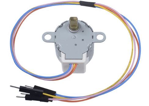
What is the Stepper Motor?
Stepper motor is a motor that converts electrical pulse signals into corresponding angular displacement (linear displacement). Each time a pulse signal is an input, the rotor rotates by an angle (one step forward), and its output angular displacement (linear displacement) is proportional to the number of input pulses, and the speed is proportional to the pulse frequency.
One digital pulse to a stepper motor drive or translator causes the motor to increment one precise angle of motion. When digital pulses increase in frequency, the step movement changes into the continuous rotation.
One application of the stepper motor will be in robots where if you want a robot arm or leg to move to an exact angle so it can grab something like a bottle, a stepper motor would be perfect! Compared to other motors, you cannot control the angle of the arm or leg but instead, it will depend on the power of the motor and the amount of electric current passing through it.
Features of stepper motors
- Every revolution of the stepper motor is divided into discrete angular movements and steps where the motor must be sent a separate pulse for each movement.
- The stepper motor can only take one step at a time and each step is the same.
- With a computer-controlled stepping, you can easily achieve precise positioning and/or speed control.
- This feature makes stepper motors very suitable for precision motion control applications
They consist of multiple coils that are organized in groups called “phases”.
Advantages of Stepper motor
- Excellent low-speed torque
Stepper motors offer excellent low-speed torque. This allows the motor to drive many loads without having to utilize any additional gearing or gearbox mechanisms.
- Safer
Compared to Servo motors, if the stepper motor breaks, it will stop automatically
- Longer life
Many moving parts of the stepper motor are frictionless. With this, stepper motors are considered to have a longer life as the bearings of the stepper motor will be the only part suffering from wear and tear.
They are also very reliable as there are no contact brushes in the motor.
- Lower cost compared to Servo Motors
Stepper motors are used in an open-loop system that does not require positional or torque feedback which makes it simpler and less costly to control.
They are also easier to set up and use. Compared to servo motors, they are better suited for low acceleration and high holding applications.
Disadvantages of Stepper motor
- Low Efficiency
Unlike DC motors, stepper motor current consumption is independent of load. They draw substantial power regardless of load.
When stepper motors are idle, they draw the most current which causes them to run hot.
- No feedback
Compared to servo motors, stepper motors have no integral feedback for the position.
Even though you can achieve precision through running open loop, limit switches or ‘home’ detectors are normally required for safety and/or to establish a reference position.
Without feedback, you cannot indicate potential missed steps.
- Torque drops rapidly with speed / Limited High-Speed Torque
Stepper motors have less torque at high speeds than low speeds.
Even though some stepper motors are optimized for better high-speed performance, they have to be paired with an appropriate driver to achieve that performance.
- It is difficult to run to a higher speed
When the load is exceeded, synchronization will be broken, and vibration and noise will be emitted when working at high speed.
When to use each motor?
When using different motors in your Arduino projects, you must pick the most suitable motor that meets your needs. Each motor has its own uses, advantages, and disadvantages which we are going to cover.
DC Motor
Application of DC motor
- DC motors are used widely in many places. Some of them are your vacuum cleaner, hairdryer, elevators, electric windows in cars, etc.
- DC motors are still used commonly due to its high starting torque (Able to deal with high resistive torques and absorb sudden rises in load effortlessly), simplicity, and also efficiency compared to other motors.
Servo Motor
Application of Servo motor
Fields that require high precision, such as machine tools, packaging equipment, textile equipment, laser processing equipment, robots, automated production lines, and other equipment that require relatively high process precision.
Stepper Motors
Application of Stepper motor
Basically, it can be used in situations involving positioning, such as ATM machines, inkjet printers, plotters, spraying equipment, medical instruments and equipment, precision instruments, industrial control systems, etc.
Getting Started with Seeed’s Arduino Motor Pack
Before we move on to the tutorials, you will need the motors! Here at Seeed, we offer our very own Arduino Motor Pack!
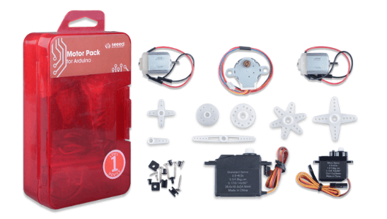
- This pack is a perfect kit for motor learning with Arduino. Whether your project requires a DC motor, a stepper motor, or a steering gear, it can be found in this kit!
- This kit consists of
- 6V DC motor(13000 rpm ±14%) x2
- Small stepper motor x1
- Standard servo x1(Speed: 0.17/60°@4.8V; 0.14/60°@6.0V)/(Torque: [email protected]; [email protected])
- Micro servo x1(Speed: 0.12/60°@4.8V; 0.10/60°@6.0V)/(Torque: [email protected]; [email protected])
- Feel that the kit is too expensive? No worries!

Currently, we are having a big sale on this Arduino Motor Pack for a limited time only!!!
Use code: MOTOR40 to get 40 percent off our Arduino motor pack now!
Without further ado, let us jump right into how to run the individual motors with the Arduino!
Arduino Motor Tutorial
Before we start, do note that you shouldn’t drive any motor directly from Arduino board pins as this may damage the board! You should use a driver circuit or motor driver to drive them!
Arduino DC Motor Tutorial
In this tutorial, we will be using an Arduino motor shield to drive the DC motor:
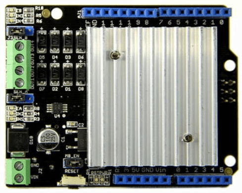
- The Motor Shield is a driver module for motors that allows you to use Arduino to control the working speed and direction of the motor.
- It is Based on the Dual Full-Bridge Drive Chip L298, it is able to drive two DC motors or a step motor. If you do not know what is L298, you can check out our other blog on L298 motor driver here!
- So how do you drive a DC motor with an Arduino motor shield?
What do you need?
- Seeeduino V4.2 (Arduino UNO Compatible Board)
- 130 DC Motor
- Motor Shield V2.0
- Jumper Cables
Step by step instructions on how to drive DC motor with Motor Shield
- Step 1
- Set SEN_A and SEN_B and connect the left 2 pins together with a jumper.
- Step 2
- Connect MB_EN together with a jumper, as we are not going use an external power.
- Step 3
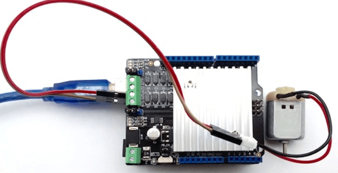
- Connect DC motor to Chanel 0 (OUT1 and OUT2) and plug Motor Shield into Arduino.
- Connect Arduino to PC via a USB cable.
- Your connection should look like this:
- Step 4
- Download Motor shield library here and install the library
- For users who do not know how to install an Arduino library, you can follow our guide on how to install and Arduino library.
- Step 5
- Upload the following code to Seeeduino:
//  Demo function:The application method to drive the DC motor.
//  Author:Loovee ([email protected])
//  2016-3-11

#include "MotorDriver.h"

MotorDriver motor;

void setup()
{
    // initialize
    motor.begin();
}

void loop()
{
    motor.speed(0, 100);            // set motor0 to speed 100
    delay(1000);
    motor.brake(0);                 // brake
    delay(1000);
    motor.speed(0, -100);           // set motor0 to speed -100
    delay(1000);
    motor.stop(0);                  // stop
    delay(1000);
}
// END FILE
Your motor should move for 1 second, stop for another second, move back for 1 second, stop for a second and loop. If nothing happens, please make sure:
- The code has been uploaded successfully
- The motor is connected properly
- The LED indicators blink right
That’s all! You have managed to run a DC motor with an Arduino Motor shield in 5 steps!
Arduino Servo Motor Tutorial
Through this tutorial, you will learn how to control a Servo Motor with your Arduino in 3 simple steps.
What do you need?
- Seeeduino V4.2 (Arduino UNO Compatible Board)
- Grove – Servo
- Base Shield V2 (For easy connection)
Step by step instructions on how to drive a Servo Motor with the Arduino
- Step 1: Connect Servo to the Seeeduino
- The Servo has three wires: power, ground, and signal.
- The power wire is typically red, and should be connected to the 5V pin on the Arduino/Seeeduino board.
- The ground wire is typically black or brown and should be connected to a ground pin on the Arduino board.
- The signal pin is typically yellow, orange or white and should be connected to D5 on the Arduino board.
- You can change to the digital port as you like, but don’t forget to change the port number in the definition of the demo code!
- Step 2: Connect the Module to the PC
- Connect the module to D5 port of Base Shield
- Plug Grove-Base Shield into Arduino
- Connect Arduino to PC via a USB cable.
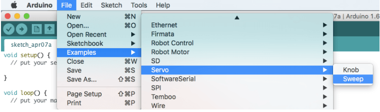
- Step 3: Software
- We will be sweeping the shaft of a servo back and forth across 180 degrees by using the Arduino Servo Library.
- Open the code directly by the path: File -> Examples ->Servo->Sweep.
/* Sweep
 by BARRAGAN <http://barraganstudio.com>
 This example code is in the public domain.

 modified 8 Nov 2013
 by Scott Fitzgerald
 http://www.arduino.cc/en/Tutorial/Sweep
*/

#include <Servo.h>

Servo myservo;  // create servo object to control a servo
// twelve servo objects can be created on most boards

int pos = 0;    // variable to store the servo position

void setup() {
  myservo.attach(5);  // attaches the servo on pin 5 to the servo object
}

void loop() {
  for (pos = 0; pos <= 180; pos += 1) { // goes from 0 degrees to 180 degrees
    // in steps of 1 degree
    myservo.write(pos);              // tell servo to go to position in variable 'pos'
    delay(15);                       // waits 15ms for the servo to reach the position
  }
  for (pos = 180; pos >= 0; pos -= 1) { // goes from 180 degrees to 0 degrees
    myservo.write(pos);              // tell servo to go to position in variable 'pos'
    delay(15);                       // waits 15ms for the servo to reach the position
  }
}
And you are done! After uploading the sketch, you should see the Servo sweep.
Arduino Stepper Motor Tutorial
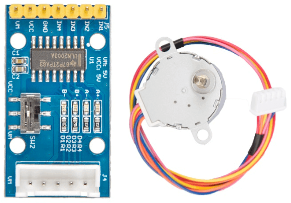
In this tutorial, we will be using the Gear Stepper Motor Driver Pack which includes a stepper motor and a motor driver board. It’s a four-phase eight-stepping stepper motor, and you can easily control this stepper motor via the drive board. You can also use this pack for position control.
What do you need?
- Seeeduino V4.2 (Arduino UNO Compatible Board)
- Gear Stepper Motor Driver Pack
- Jumper Cables
Step by step instructions on how to drive a Stepper Motor with the Arduino
- Step 1
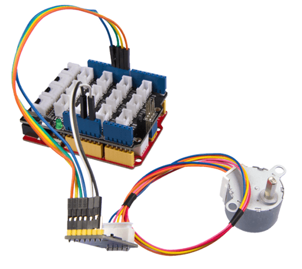
- Connect the Gear Stepper Motor Driver Board to your Seeeduino via the jumper cables
| Seeeduino V4.2 | Gear Stepper Motor Driver board |
| Digital Pin 8 | IN1 |
| Digital Pin 9 | IN2 |
| Digital Pin 10 | IN3 |
| Digital Pin 11 | IN4 |
| GND | GND |
| VCC_5V | VCC |
| VCC_5V | VM |
You can connect the VM pin to VCC_5V or you can just do not use it as long as you choose the VCC in the switch.
- Step 2
- Plug the stepper motor into the Gear Stepper Motor Driver Board.
- Step 3
- Connect Seeeduino to PC via a USB cable.
- Your connection should look like this now:
- Step 4
- Copy the following code into a new sketch in the Arduino IDE.
int pwm1=9;
int pwm2=10;
int ctr_a =9;
int ctr_b =8;
int ctr_c =11;
int ctr_d =10;
int sd =6;
int i=0;
int t=1500;

void setup()
{
    //pinMode(sd,OUTPUT);
    //pinMode(pwm1,OUTPUT);
    //pinMode(pwm2,OUTPUT);
    pinMode(ctr_a,OUTPUT);
    pinMode(ctr_b,OUTPUT);
    pinMode(ctr_c,OUTPUT);
    pinMode(ctr_d,OUTPUT);
    delay(1);
    //digitalWrite(sd,HIGH);
    //digitalWrite(pwm1,HIGH);
    //digitalWrite(pwm2,HIGH);
//    digitalWrite(ctr_a,LOW);
//    digitalWrite(ctr_b,LOW);
//    digitalWrite(ctr_c,LOW);
//    digitalWrite(ctr_d,LOW);

}


void loop ()
{
//   for(i=1500;i>=1;i--)
//   {
//       digitalWrite(ctr_a,HIGH);//A
//       digitalWrite(ctr_b,LOW);
//       digitalWrite(ctr_c,LOW);
//       digitalWrite(ctr_d,LOW);
//       delay(t);
//       digitalWrite(ctr_a,HIGH);
//       digitalWrite(ctr_b,HIGH);//AB
//       digitalWrite(ctr_c,LOW);
//       digitalWrite(ctr_d,LOW);
//       delay(t);
//       digitalWrite(ctr_a,LOW);
//       digitalWrite(ctr_b,HIGH);//B
//       digitalWrite(ctr_c,LOW);
//       digitalWrite(ctr_d,LOW);
//       delay(t);
//       digitalWrite(ctr_a,LOW);
//       digitalWrite(ctr_b,HIGH);
//       digitalWrite(ctr_c,HIGH);//BC
//        digitalWrite(ctr_d,LOW);
//       delay(t);
//       digitalWrite(ctr_a,LOW);
//       digitalWrite(ctr_b,LOW);
//       digitalWrite(ctr_c,HIGH);//C
//       digitalWrite(ctr_d,LOW);
//       delay(t);
//       digitalWrite(ctr_a,LOW);
//       digitalWrite(ctr_b,LOW);
//       digitalWrite(ctr_c,HIGH);//CD
//       digitalWrite(ctr_d,HIGH);
//       delay(t);
//        digitalWrite(ctr_a,LOW);
//       digitalWrite(ctr_b,LOW);
//       digitalWrite(ctr_c,LOW);//D
//       digitalWrite(ctr_d,HIGH);
//       delay(t);
//        digitalWrite(ctr_a,HIGH);
//       digitalWrite(ctr_b,LOW);
//       digitalWrite(ctr_c,LOW);//DA
//       digitalWrite(ctr_d,HIGH);
//       delay(t);
//
//   }
//       digitalWrite(ctr_a,LOW);
//       digitalWrite(ctr_b,LOW);
//       digitalWrite(ctr_c,LOW);
//       digitalWrite(ctr_d,LOW);
//
//
//
//     for(i=1500;i>=1;i--)
//   {
//
//       digitalWrite(ctr_d,HIGH);//D
//       delay(t);
//       digitalWrite(ctr_c,HIGH);//DC
//       delay(t);
//       digitalWrite(ctr_d,LOW);//C
//       delay(t);
//       digitalWrite(ctr_b,HIGH);//CB
//       delay(t);
//       digitalWrite(ctr_c,LOW);//B
//       delay(t);
//       digitalWrite(ctr_a,HIGH);//BA
//       delay(t);
//       digitalWrite(ctr_b,LOW);//A
//       delay(t);
//       digitalWrite(ctr_d,HIGH);//AD
//       delay(t);
//       digitalWrite(ctr_a,LOW);
//       digitalWrite(ctr_d,LOW);
//   }

   for(i=1500;i>=1;i--)
   {
       digitalWrite(ctr_a,LOW);//A
       digitalWrite(ctr_b,HIGH);
       digitalWrite(ctr_c,HIGH);
       digitalWrite(ctr_d,HIGH);
       delayMicroseconds(t);
       digitalWrite(ctr_a,LOW);
       digitalWrite(ctr_b,LOW);//AB
       digitalWrite(ctr_c,HIGH);
       digitalWrite(ctr_d,HIGH);
       delayMicroseconds(t);
       digitalWrite(ctr_a,HIGH);
       digitalWrite(ctr_b,LOW);//B
       digitalWrite(ctr_c,HIGH);
       digitalWrite(ctr_d,HIGH);
       delayMicroseconds(t);
       digitalWrite(ctr_a,HIGH);
       digitalWrite(ctr_b,LOW);
       digitalWrite(ctr_c,LOW);//BC
        digitalWrite(ctr_d,HIGH);
       delayMicroseconds(t);
       digitalWrite(ctr_a,HIGH);
       digitalWrite(ctr_b,HIGH);
       digitalWrite(ctr_c,LOW);//C
       digitalWrite(ctr_d,HIGH);
       delayMicroseconds(t);
       digitalWrite(ctr_a,HIGH);
       digitalWrite(ctr_b,HIGH);
       digitalWrite(ctr_c,LOW);//CD
       digitalWrite(ctr_d,LOW);
       delayMicroseconds(t);
        digitalWrite(ctr_a,HIGH);
       digitalWrite(ctr_b,HIGH);
       digitalWrite(ctr_c,HIGH);//D
       digitalWrite(ctr_d,LOW);
       delayMicroseconds(t);
       digitalWrite(ctr_a,LOW);
       digitalWrite(ctr_b,HIGH);
       digitalWrite(ctr_c,HIGH);//DA
       digitalWrite(ctr_d,LOW);
       delayMicroseconds(t);

   }
//       digitalWrite(ctr_a,HIGH);
//       digitalWrite(ctr_b,HIGH);
//       digitalWrite(ctr_c,HIGH);
//       digitalWrite(ctr_d,HIGH);
//


//     for(i=1500;i>=1;i--)
//   {
//
//       digitalWrite(ctr_d,HIGH);//D
//       delay(t);
//       digitalWrite(ctr_c,HIGH);//DC
//       delay(t);
//       digitalWrite(ctr_d,LOW);//C
//       delay(t);
//       digitalWrite(ctr_b,HIGH);//CB
//       delay(t);
//       digitalWrite(ctr_c,LOW);//B
//       delay(t);
//       digitalWrite(ctr_a,HIGH);//BA
//       delay(t);
//       digitalWrite(ctr_b,LOW);//A
//       delay(t);
//       digitalWrite(ctr_d,HIGH);//AD
//       delay(t);
//       digitalWrite(ctr_a,LOW);
//       digitalWrite(ctr_d,LOW);
//   }


}- Step 5
- Upload the demo. If you do not know how to upload the code, please check our tutorial here on How to upload code.
- If everything is uploaded properly, the motor should run like this:

Summary
That’s all on how to get started with Arduino motors – DC, Stepper, Servo Motor! The Arduino has always been popular when it comes to running motors and today we have just covered 3 of them! If you have any questions on how to drive a DC, Servo or stepper motor using the Arduino, please feel free to leave them down in the comments below!
Interested in our actuators and motor products? You can check out all of our motor products here!