What is Pulse Width Modulation (PWM)? Applications and Accessories
Having trouble changing the brightness of the LED in your project? Directly changing the power supply voltage in the circuit to accomplish that isn’t easy. But you can use Pulse Width Modulation (PWM) to help you with that! This can be easily implemented by coding in Arduino.
In this tutorial, I will cover the following :
- What is Pulse Width Modulation(PWM)?
- Duty Cycle and Frequency of PWM
- Application of Pulse Width Modulation(PWM)
- Implementing PWM with Arduino
- PWM Related Accessories
What is Pulse Width Modulation(PWM)?
Pulse Width Modulation(PWM) is a digital technology that uses the amount of power delivered to a device that can be changed. It generates analogue signals by using a digital source. A PWM signal is basically a square wave which is switched between on and off state. The duty cycle and frequency of a PWM signal determine its behaviour.
Duty Cycle in PWM
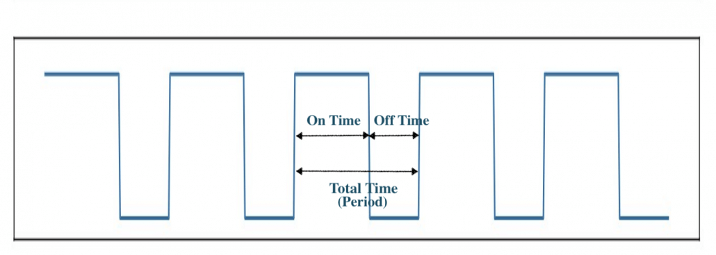
The duty cycle of the PWM signal refers to the ratio of the time that the signal is in a high(on) state over the total time it takes to complete one cycle. It is commonly expressed as a percentage or a ratio.
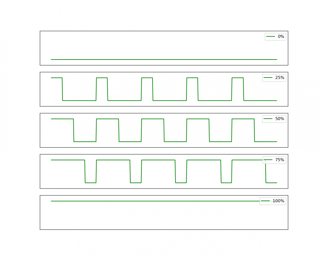
A 50% duty cycle means that the high state takes half of the time and the low state takes the other half of the time, this is the same as an ideal square wave. If this ratio is greater than 50%, the logic high signal takes a longer time than logic low, vice versa. Thus, a 100% duty cycle means the signal is always on(full-scale), and the 0% duty cycle means the signal is always off(grounding).
Frequency of PWM signal
A period is equal to the time this signal completes a one-and-off cycle. The frequency is the number of times a periodic change is completed per unit time and it is the inverse of the period. It determines the speed at which the PWM completes one cycle, which means the speed at which the signal switches between high and low states. If we turn the digital signal on and off repeatedly with a high enough frequency, the output will behave like an analogue signal with a constant voltage.
Application of Pulse Width Modulation(PWM)
Adjust Brightness of Screen using PWM
For PWM, adjusting the brightness of the screen does not rely on the power but by alternating on and off of the screen. When the PWM dimming screen is lit, it does not continuously emit light, but it constantly lights up and turns off the screen. If this changes fast enough, our eyes treat is as always on but with different brightness based on different duty cycles. The larger the duty cycle, the brighter the screen.
Other PWM Applications
There are other applications that use PWM technology, including:
- Drive buzzer with different loudness
- Control speed of the motor
- Control the direction of a servo
- Provide an analog output
- Generate audio signal
- Telecommunication: Encode message
Implementing PWM with Arduino
PWM can be implemented in various ways on Arduino. On Seeeduino board, there are 6 pins(i.e. pin 3, 5, 6, 9, 10, 11 ) which can output a PWM wave with analogWrite() function. Calling the AnalogWrite() function allows a stable square wave with a specified duty cycle to be generated on the PWM pins. Generally, the frequency of these pins are about 490Hz, and the pin 5 and 6 of Seeeduino or its similar boards have the frequency of 980Hz.
The output voltage from Arduino pins are 5V, and different duty cycles output different voltage levels as stated below:
| Duty Cycle | Output Voltage Levels |
| 0% | 0V |
| 25% | 1.25V |
| 50% | 2.5V |
| 75% | 3.75V |
| 100% | 5V |
Adjust the Brightness of LED
To control the brightness of an LED with Arduino with the PWM technique. You can follow the example below:
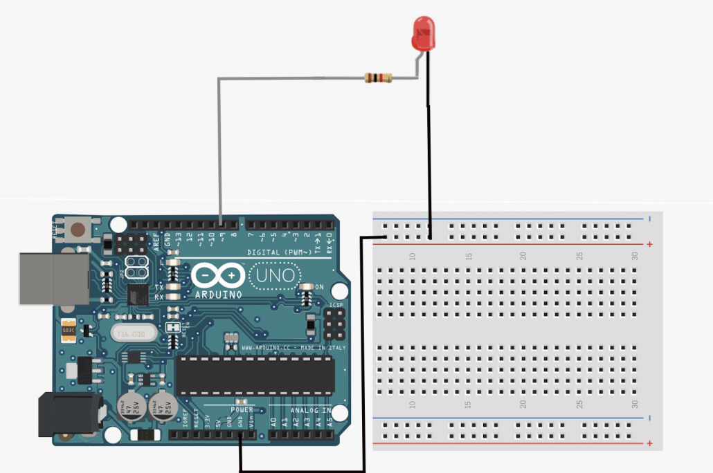
Hardware Connection
Software
analogWrite() Function Syntax:
analogWrite ( pin , value ) ;
The value representing the duty cycle, and the number is between 0(off) and 255(on).
int ledPin = 9; // LED connected to digital pin 9

void setup() {
   pinMode(ledPin, OUTPUT); // sets the pin as output
}

void loop() {
   analogWrite(ledPin, 255); //set duty cycle to always on
}
You can change ‘255’ to any number between 0~255 for different outputs, or you can modify the code to change the value continuously.
PWM Related Accessories
Grove – 16-Channel PWM Driver (PCA9685)
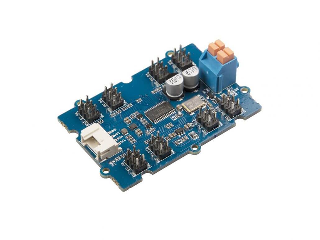
Have you ever felt anxious because of the limited number of development board PWM output interfaces? Don’t worry! The Grove – 16-Channel PWM Driver is based on NXP PCA9685, which is a 16-Channel 12bit I2C PWM driver. This PCA9685 16-Channel 12bit I2C PWM driver board can drive up to 16 servos with external power supply.
Based on the features of NXP PCA9685, this PWM driver board can well meet the needs of multi-channel PWM projects, such as a hexapod walker, MarsCar. Additionally, you can use this board as a LED controller. You can easily control this driver board through the I2C Grove interface.
Motor Pack for Arduino
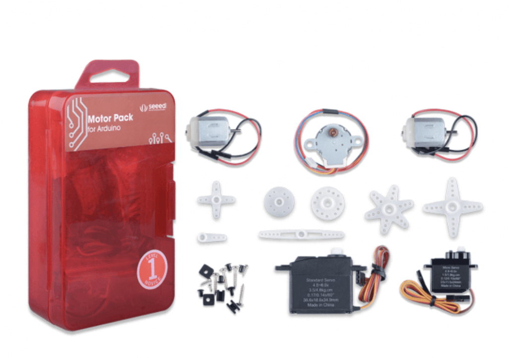
Motor Pack for Arduino is a perfect kit for you to learn motor with Arduino. Whether your project requires a DC motor, a stepper motor, or a steering gear, all of them can be found in this kit! But do you know how to use PWM to control the motor?
Use PWM for Motor Control
For a DC motor, when the load (torque) of the motor is constant, the speed is proportional to the power supply voltage. As discussed above, the output voltage level is determined by the duty cycle of PWM, thus the PWM can be used to control the speed of the motor.
Hardware Connection
Similar hardware connection would apply to Motor as well.
- Connect Motor to pin 9 and GND.
- You might need to connect a voltage regulator between motor and Arduino, because Arduino can only output voltage which is up to 5V.
Software
analogWrite() Function Syntax:
analogWrite ( pin , value ) ;
The value representing the duty cycle, and the number is between 0(off) and 255(on).
int ledPin = 9; // LED connected to digital pin 9

void setup() {
   pinMode(ledPin, OUTPUT); // sets the pin as output
}

void loop() {
   analogWrite(ledPin, 255); //set duty cycle to always on
}
You can change ‘255’ to any number between 0~255 for different outputs, or you can modify the code to change the value continuously.
Summary
And that’s all on PWM! Have you learnt something new through this blog? Hope that we managed to help you with your projects, happy tinkering!