Analog-to-digital converter——ADS1115
ADS1115 is an ultra-small, low-power, 16-bit precision AD converter (Analog to Digital Converter) with an internal reference voltage. Mainly used in high-precision instrumentation, automotive electronics, battery voltage collection and other high-precision collection occasions. Its general function is to amplify, improve accuracy, and convert analog to digital for data analysis.

How do ADS1115 work?
ADS1115 has an onboard reference and oscillator. Data is transmitted through an I2C compatible serial interface; 4 I2C slave addresses can be selected. ADS1115 uses a single working power supply ranging from 2.0V to 5.5V.
The ADS1115 can perform conversion operations at a rate of up to 860 samples per second (SPS). The ADS1115 has an onboard programmable gain amplifier (PGA) that can provide an input range as low as ±256mV from the power supply voltage, thus enabling the measurement of large and small signals with high resolution. In addition, the ADS1115 also has an input multiplexer (MUX), which can provide 2 differential inputs or 4 single-ended inputs.
ADS1115 can work in continuous conversion mode or single trigger mode, the latter will automatically power off after a conversion is completed, thereby greatly reducing the current consumption in the idle state. ADS1115 has a specified temperature range from -40°C to +125°C.
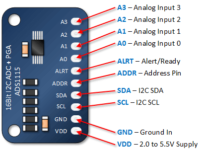
Pin function of ADS1115
| Pins | Function |
| VDD | Power supply pin. Generally, the voltage difference between VDD and GND is 2-5.5V |
| GND | Ground terminal |
| ALERT | The result output of the comparator |
| SCL, SDA | Communicate with other devices |
| ADDR | Address side |
| A0, A1, A2, A3 | Input terminals |
The connection between ADS1115 and MCU:
VDD——>3.3/5V of MCU
GND——>SCM GND
ADDR——>Generally connected to ground
A0-3——>Connect to the input voltage line
SCL, SDA -> SCL, SDA of the microcontroller
ALERT——>Dangling
Product features of ADS1115
- Low power consumption: 150uA in continuous mode
- Conversion rate: 8Bps to 860Bps
- Internal oscillator
- Built-in reference voltage: The internal reference voltage can be set by configuring the internal register.
- IIC interface: Address can be programmed through pins, and there are typically three operating modes for communication frequency
- ADS1115 supports the following 3 modes:
- Standard mode: Maximum 100KHz
- Fast mode: maximum 400KHz
- High-speed mode: up to 3.4MHz
- Four single-channel inputs or two differential inputs
- Reference input positive and negative pressure: ADS1115 can collect positive and negative pressure.
- Reference input positive pressure digital acquisition output range: 0-32767 (from small to large)
- Reference input negative pressure digital acquisition output range: 32768-65535 (from small to large)
If the internal reference voltage of ADS1115 is set to 4.096V, the positive voltage acquisition accuracy is 4.096V/2^15 = 0.125mV.
- Initialization: ADS1115 related registers are initialized when power is on.
- Operation mode: a single conversion and a continuous conversion.
ADS1115 and IIC
ADS1115 data communication adopts IIC interface and follows the IIC communication protocol, so there are two operations to communicate with the single-chip microcomputer. One: The IIC communication protocol is simulated through the I/O of the microcontroller to interact with it. Two: Use the microcontroller with the IIC interface to interact with it. In order to ensure the stability of the data exchange, the related steps should be configured strictly in accordance with the IIC protocol (start signal, stop signal, restart signal, response signal) and cannot be omitted.
IIC is a half-duplex communication protocol that can only receive or send at the same time.
There are generally four kinds of signals: start signal, end signal, nck signal, nack signal.
Read data
Reading data steps
1. Generate IIC start signal
2. Sending address
3. Send a read operation command (2.3 together into 8 bits)
4. Wait for the response
5. Read data
6. Generate end signal
Write data
1. Generate IIC start signal
2. Sending address
3. Send the write operation command (2.3 together into 8 bits)
4. Wait for the response
5. Write data
6. Generate end signal
Raspberry Pi uses ADS1115 module to read analog signals
Raspberry Pi is a common main control board with powerful functions. The 16-bit AD conversion module of ADS1115 is specially designed for Raspberry Pi and Gravity series analog sensors, which can greatly reduce the difficulty of using analog sensors on the Raspberry Pi main control board. It is plug-and-play and requires no soldering, which is very convenient. The Gravity series of sensors are numerous and rich in types, which can meet the needs of various sensors for the Raspberry Pi main control board.
One AD module can read 4 channels of analog signals. Since the onboard I2C has an address selection switch function, it supports the cascading of 2 AD modules and reads 8 analog signal channels, which is sufficient to meet the needs of various scenarios.

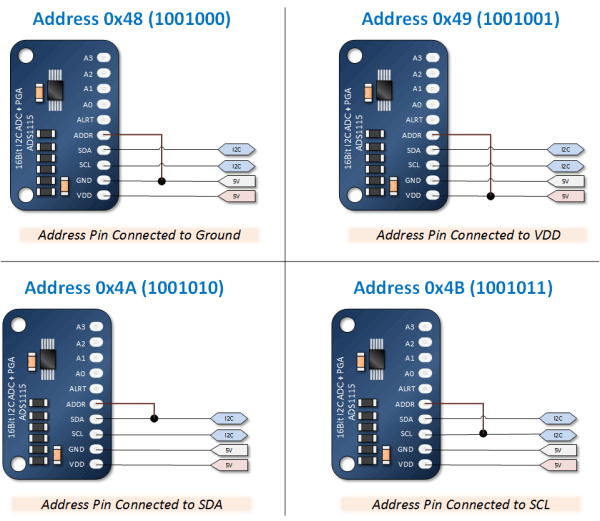
In addition to the basic connection, our ADDR interface also needs to be connected to the corresponding interface.
Each device can use different address pin configurations to connect up to four ADS111x devices to a single I2C bus. Use the address pins to set the ADS111x to one of four different I2C addresses. Use GND, VDD and SCL addresses first. If using SDA as the device address, keep the SDA line for at least 100 ns after the SCL line goes low to ensure that the device decodes the address correctly during I2C communication.
The development of a product is inseparable from PCB assembly. For more details about the product ADS1115, please click Seeed Fusion.