Rotary Encoders – How it works, How to use it with Arduino
A rotary encoder is a position sensor used to determine the angular position of a rotating shaft. It can be used with an Arduino through modules to achieve such functionality. With two main types of rotary encoder available (Absolute encoder and Incremental encoder) that adopt different functional technologies, one would beg to wonder how does all of them work?

Hence, in today’s rotary encoder tutorial, I’ll be going through all you need to know about rotary encoders and how you can get started using it with Arduino!
Types of Rotary Encoders and How does it work?
Mechanical Absolute Rotary Encoders

An absolute rotary encoder is one that measures an absolute angle of the encoded shaft through having a unique code for each shaft position. With that, every position of the measurement range/angle is being identified by a certain code on a disc. This means negates the need for counters as positional values are always directly available even when power is removed from the encoder.
A mechanical absolute encoder is a common low-cost option that is constructed with a metal disc and works as follow:
- A metal disc on a shaft is used in conjunction with a stationary pickup device and rotates
- When the shaft rotates, a unique code pattern is produced
- Which means each position of the shaft has a pattern
- This pattern is used to determine the exact position
The above explanation applies to how a mechanical absolute rotary sensor works, but there are two other ways to detect rotational position changes; Optical or magnetic sensors changes. We’ll discuss these two sensing methods below.
Optical Absolute Rotary Encoders
Optical absolute rotary encoders are constructed with either glass or plastic material disc with transparent and opaque surface areas to allow the light source and photodetector to detect optical patterns. Such detection helps in determining the disc position at any point in time.
The process of determining position with optical rotary encoders:
- Disk attached to the shaft rotates
- Depending on the pattern of the disk, the light that passes through is either transmitted or blocked
- Transmitted light that’s received is converted to electrical currents in the photodetector
- Current converted then becomes digital signals to determine the position, speed, angle, etc.
Magnetic Absolute Encoders

Magnetic absolute encoders are constructed with a series of magnetic poles to represent encoder position and sensors which are typically Hall Effect or magnetoresistive. It shares a similar working principle of optical encoders, but instead of light, sensors detect a change in magnetic fields.
The process of determining position with magnetic rotary encoders:
- Disk attached rotates
- Magnetic sensors detect the change in the magnetic field due to rotation
- Such changes are converted into sine waves and amplified into digital signals to produce the desired output
Incremental Encoder
As compared to absolute encoders, the incremental encoder works by reading changes in angular displacement instead of reading an absolute angle of the encoded shaft.
How incremental encoder work

Also known as a quadrature, a rotary incremental encoder has two output signals, A and B, issuing square waves when the encoder shaft rotates. The square wave frequency indicates the speed of shaft rotation, while the A-B phase relationship indicates the direction of rotation.
Whereas some rotary incremental encoders determine the amount of rotation through a separate counter that counts the number of pulses outputted in response to the amount of rotational displacement of the shaft.
Such rotary incremental encoders go through such process of determining position with magnetic rotary encoders:
- Rotary displacement of the shaft occurs
- Resulting from that, the encoder outputs a pulse string accordingly
- A separate counter placed at the reference point then counts the number of pulses to produce the desired output
Rotary Encoders vs Potentiometer
To further understand rotary encoders, what better way than to compare it to its closest comparison; potentiometer since when considering devices that sense rotation of a shaft, it’s normally between either.
Without going heavy in the comparative details between the two, here’s why rotary encoders are the more preferred option nowadays:
- Digital input as compared to Analog input, making it easily parable with a microcontroller for translation of output
- Ability to rotate continuously, providing excellent resolution
- Clear angular position, with higher precision, known-contact and no rotation angle limitation
However, with that said, there are still digital potentiometer available that provide easy pairing with microcontroller boards
Selecting a Rotary Encoder and Application
To ease your selection process in choosing a rotary encoder for your next Arduino project, we’ve prepared some of our recommendations here from Seeed! You’ve probably already seen these placements earlier but here’s a breakdown of what each option has to offer.
Rotary Encoder with Switch

Need a simple rotary encoder to help you get started in sensing rotation shaft with Arduino? This recommended option is the one for you!
With a total of 5 pins, 3 on one side for rotary encoding which need a simple circuit to supply DC 5V while the other two go short whenever pressed, you’re not short of any functionality when using this!
If you’re interested to find out more and how you can use this rotary encoder with Arduino, do check out our product page!
Grove – 12-bit Magnetic Rotary Position Sensor / Encoder (AS5600)

Need an option that can both work as a magnetic potentiometer or magnetic encoder with excellent reliability and durability? This option is for you!
Not only does it work both ways, but when compared with a traditional encoder/potentiometer, the Grove – AS5600 is a non-contact, no angle rotation limited and high precision option!
- All made possible with the onboard AS5600 that’s based on the Hall Effect, the built-in Hall sensor
Interfacing with Arduino is made simple through our onboard Grove Interface, allowing for plug and play instead of Jumper wires and breadboarding!
If you’re interested to find out more; its datasheet and how you can use this rotary encoder with Arduino, do check out our product page!
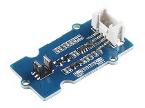
Grove – Optical Rotary Encoder

Keeping the best for last is this optical rotary encoder that includes an infrared emitter and two phototransistor detectors. Suitable for not only rotary encoder usage to detect speed/rotation, but rotation direction as well!
Its features include:
- Double phototransistor detectors, can determine the direction of rotation
- On-board LED indicators
- Grove Interface for ease of usage with Arduino
Applications:
- Automotive optical sensors
- Accurate position sensor for encoder
- Sensor for motion, speed, and direction
- Sensor for “turn and push” encoding
Note: We’ll be using this rotary encoder for our Arduino tutorial afterwards, but if you’re looking to find out more information on it, you can head to our product page!
Rotary Encoder Tutorial with Arduino
Now we’ve understood about the principles of Rotary Encoder, let us show you how you can start using one with Arduino through this tutorial!
What you’ll need for this tutorial:
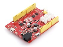
- Seeeduino is Seeed’s very own Arduino board, built with relative advantages over the original
- If you wish to use an Arduino board for this tutorial, it’s applicable for these boards
- Arduino UNO, Arduino Mega, Arduino Leonardo, Arduino 101, Arduino Due
Before we begin with assembling the hardware, do take note of the following:
- Gently plug in the USB cable to avoid damaging the port and ensure you’re using the USB cable with 4 wires instead of 2 as it can’t transfer data
Hardware Assembly and Pinout:
Before we assemble the hardware together, here’s a hardware overview of the rotary encoder that we’re using with its pinout:

Hardware Assembly:
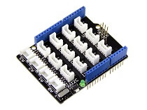
- Step 1: Connect the Grove – Optical Rotary Encoder to port D5 of the Base Shield
- Step 2: Plug Grove – Base Shield into Seeeduino
- Step 3: Connect Seeeduino to PC via a USB cable
It should look something like this after completing the above steps:

Software Configurations and Arduino Library Code
- Step 1: Install the Encoder Library in the Arduino IDE by hovering your cursor to Sketch -> Include Library -> Manage Libraries

- Step 2: Search for the encoder in the pop-up window and find Encoder by Paul Stoffregen, choose the Version 1.4.1 and click install

When the library is installed, you’ll see the status turn to “installed” and you can now click close

- Step 3: Restart the Arduino IDE. Open the example in either the following three ways:
- Open it directly in Arduino IDE via the path: File -> Examples -> Encoder -> Basic
- Open it in your computer by clicking the Basic.pde which you can find in the xxxx\Arduino\libraries\Encoder\examples\Basic, XXXX is the location you installed the Arduino IDE
- Copy and paste the following code into a new sketch in Arduino IDE
Arduino Code:
/* Encoder Library - Basic Example
 * http://www.pjrc.com/teensy/td_libs_Encoder.html
 *
 * This example code is in the public domain.
 */

#include <Encoder.h>

// Change these two numbers to the pins connected to your encoder.
//   Best Performance: both pins have interrupt capability
//   Good Performance: only the first pin has interrupt capability
//   Low Performance:  neither pin has interrupt capability
Encoder myEnc(5, 6);
//   avoid using pins with LEDs attached

void setup() {
  Serial.begin(9600);
  Serial.println("Basic Encoder Test:");
}

long oldPosition  = -999;

void loop() {
  long newPosition = myEnc.read();
  if (newPosition != oldPosition) {
    oldPosition = newPosition;
    Serial.println(newPosition);
  }
}
Quick Tip: You can change two no. to the pins connected to your encoder. For the best performance; both pins have interrupt capability, so you can change the code line 13 into Encoder myEnc (2, 3). Meanwhile, you should connect the sensor to port D2 of the base shield.
- Step 4: Upload the demo. If you’re unsure on how to do so, do check out our guide on how to upload a code
- Step 5: Open the Serial Monitor of Arduino IDE by clicking Tool -> Serial Monitor or tap the Ctrl + Shift + M key on your keyboard. Set baud rate to 9600
If you’ve followed the above tutorial step by step, you should achieve success and getting the below result:
Basic Encoder Test:
0
1
2
3
4
3
2
1
0
-1
-2
-3
-4
Now when you move the obstacle from left to right, the count value will increase by 1, and when you move the obstacle from right to left, the count value will decrease by 1!
Summary
That’s all for today’s guide on Rotary encoders and how you can use it with Arduino. I hope with this, you get a basic understanding of what are rotary encoders, how it works as well!