RFID – How does it work and How to use it with the Arduino

RFID, short for Radio-Frequency Identification, are used in many industries. For example, an RFID tag can be used to attached or implanted in almost everything where it is then used for identification and tracking purposes.
Today, through today blog, we are going to talk about:
- Why use RFID
- How does RFID works
- RFID Frequency of Operation
- Tutorial: RFID Module Interfacing with the Arduino
Why use RFID?
Firstly, why use RFID?
- Some advantages of using RFID includes:
- Speed and productivity (RFID is able to read hundreds of tags at once)
- Ease of use (Tags do not need to be in the line of sight of the RFID reader to be able to read it)
- RFID tags and labels can be very durable (Can withstand harsh environments and temperatures)
- RFID tags can hold more data than other types tags and labels (Up to 100 times the data of bardcodes)
- There is a variety of range for RFID from 10cm up to 150m!
- Tags are reusable (Rewritten and used again)
- Security purposes (Tags can be encrypted or locked, each tag can have a unique product code)
How does RFID works?
- RFID uses wireless non-contact radio frequency to transfer data for identification and tracking purposes.
- There are 2 parts to a typical RFID system:
RFID Tag
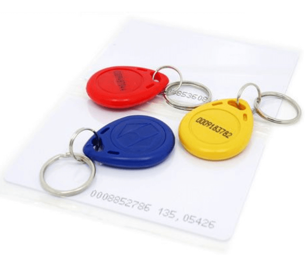
- The tag, often a key chain or card, are attached to the object. The tag contains a chip for storing information regarding the attached object and also an antenna to receive and transmit signals.
- Each tag will also have its own identification called UID also known as unique identification number.
- The tags can be passive or active where:
- Passive Tag = Does not have a battery, energy is transmitted by the RFID reader
- Active Tag = Built-in battery, similar features as passive tags but are able to send a stronger signal to the reader which increases the range of the tag.
RFID Reader
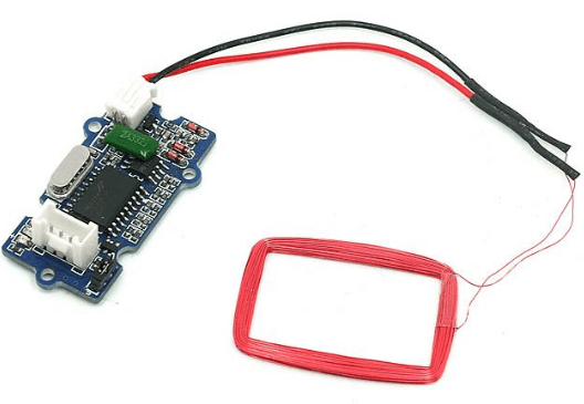
- The RFID reader has 3 parts to it:
- Radio frequency module
- Control unit
- Antenna coil
- The RFID reader acts mainly as a transceiver (transmit and receive).
- The RFID reader can also come in a module or an electronic brick.
RFID working protocol
- Step 1
- The RFID reader will generate a high frequency electromagnetic field when a tag is nearby caused by induction.
- Step 2
- After the electromagnetic field is generated and detected by the tag, due to mutual coupling a voltage is then generated by the tag antenna coil by induction which then serves as power for the tag.
- Step 3
- The tag will then, in return, converts the signal in power and responds to the transceiver using a technique called load modulation.
RFID Frequency of Operation
- RFID tags are operated at a few frequencies which affects their signals range. They are:
- Low Frequency (LF) = 125 kHz or 134 kHz = Range of up to 10cm
- High Frequency (HF) – 13.56 MHz = Range of up to 1m
- Ultra high Frequency (UHF) – 860 to 960 MHz = Range of 10m to 15m
RFID Module Interfacing with the Arduino
So now you’ve got a basic understanding on the RFID working protocol, it is now time for you to put the knowledge into use! Today, we will have a short tutorial on how to use RFID together with the Arduino!
What do you need?
- Seeeduino V4.2 – Seeed’s very own Arduino
- Base Shield V2 – Optional, to make connections easier
- Grove – 125KHz RFID Reader
- RFID tag combo (125khz) – 5 pcs
For this tutorial, we will be using a 125KHz RFID reader which has a range of up to 10cm.
Step by step instructions to interface your RFID module with Arduino
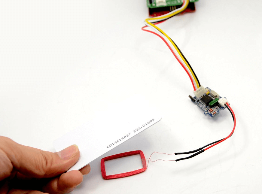
- Step 1:
- Connect the Grove – 125 KHz RFID reader to port D2 of the Grove Base Shield V2 and plug Base Shield into Seeduino
- If you do not have a Grove Base Shield V2, you can directly connect the RFID reader to the Seeeduino as follows:
| Seeeduino | Grove – 125KHz RFID Reader |
|---|---|
| 5V | Red |
| GND | Black |
| D3 | White |
| D2 | Yellow |
- Step 2
- Connect Seeeduino to PC via a USB cable
- Step 3
- Copy the following code as shown below into Arduino IDE and upload. If you do not know how to upload the code, you can refer to our guide on how to upload code.
/*
  link between the computer and the SoftSerial Shield
  at 9600 bps 8-N-1
  Computer is connected to Hardware UART
  SoftSerial Shield is connected to the Software UART:D2&D3
*/

#include <SoftwareSerial.h>

SoftwareSerial SoftSerial(2, 3);
unsigned char buffer[64];       // buffer array for data receive over serial port
int count = 0;                    // counter for buffer array

void setup()
{
    SoftSerial.begin(9600);     // the SoftSerial baud rate
    Serial.begin(9600);         // the Serial port of Arduino baud rate.
}

void loop()
{
    // if date is coming from software serial port ==> data is coming from SoftSerial shield
    if (SoftSerial.available())
    {
        while(SoftSerial.available())               // reading data into char array
        {
            buffer[count++] = SoftSerial.read();      // writing data into array
            if(count == 64)break;
        }
        Serial.write(buffer, count);     // if no data transmission ends, write buffer to hardware serial port
        clearBufferArray();             // call clearBufferArray function to clear the stored data from the array
        count = 0;                      // set counter of while loop to zero
    }
    if (Serial.available())             // if data is available on hardware serial port ==> data is coming from PC or notebook
    SoftSerial.write(Serial.read());    // write it to the SoftSerial shield
}
void clearBufferArray()                 // function to clear buffer array
{
    // clear all index of array with command NULL
    for (int i=0; i<count; i++)
    {
        buffer[i]=NULL;
    }
}- Step 4
- Open the Serial Monitor and the card or tag information can be displayed as shown below:
- Open the Serial Monitor and the card or tag information can be displayed as shown below:
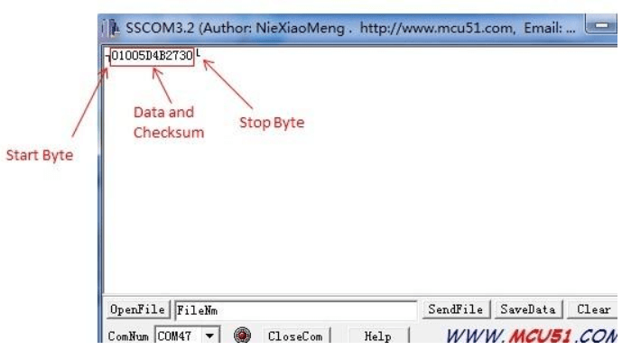
- You should be able to read an RFID tag or card using the Grove – 125 KHz RFID reader using your Arduino now!
Here are some frequently asked questions:
How to convert the output to Card Number
- To convert the out to card number,
- Take ID: 0009776930 for example:
- Card Number ID: 0009776930 ——- Decimalism [Start Bit(00) + Card Number(8 numbers)]
- Output: 0700952F229F ————- Hex [[Start Bit(07h) + Card Number(8 numbers) + Checksum]
- The calculator for decimal and hex numbers are available online.
How to read tags continuously?
- The RFID reader can read tags continuously without any setting. Keep the tag 2.5-4 cm from the antenna, and the reader can read data continuously. And if the distance is below 2.5cm, the reader reads data once if not moving tags away.
Wiegand Mode
- You can also set your Arduino into Wiegand mode where it is able to receive data directly from any Wiegand device such as the Grove – 125 KHz RFID Reader and also output the data in the Wiegand format.
- To set it to Wiegand mode:
- (Jumper Set to the Right two Pins) You would need to select the jumper to “W” to enter this mode. The Wiegand demo code for Seeeduino is designed to read Wiegand data in interrupt mode.
- In Wiegand Mode, output data is formatted with 26bits including 24bits card info and 2 bits parity.
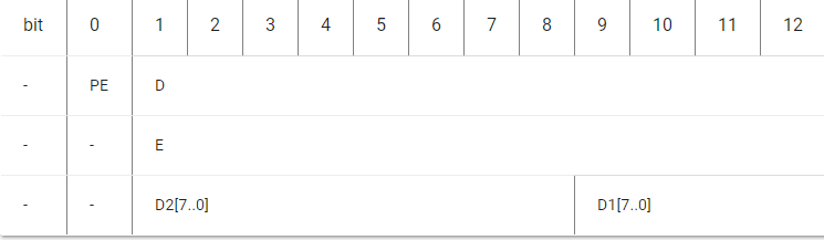
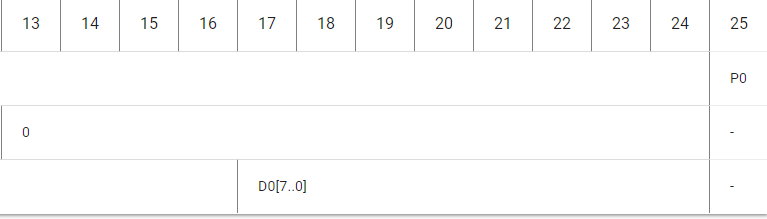
- PE is even bit, PO is odd bit;
- E is the data bit which was involved in even, O is the data bit which was involved in odd;
- DX[7..0] is the data bit which correspond to Mifare@ Standard & Light card read only ID;
That’s all! You have successfully connected your Arduino to your Grove – 125KHz RFID Reader. Here are some resources for you regarding the Grove – 125 KHz RFID reader:
- [Demo] Grove – 125KHz RFID Reader Demo
- [PDF] Declaration of conformity
- [PDF] Test Report
Summary
That is all for RFID – How does it work and How to use it with the Arduino! If you have any questions, do feel free to leave them down in the comments section down below! Want to do more with the RFID? Why not try building your own Arduino based security project using Cayenne!
Other than 125Khz readers and tags, we also offer modules and 13.56 MHz RFID readers and tags with a range of 1m! Interested? Check out all our RFID products here.