What is MOSFET Transistor and How to use with Arduino?
Stumbled upon MOSFET (metal-oxide-semiconductor field-effect transistor) but find it complex to understand what it is and how to use it with Arduino? Not to worry, in today’s guide, we’ll go through the Basics of MOSFET, its working principle, and how you can use it with an Arduino board!
Do note that this guide will aim to explain MOSFET through the simplest way possible! For the full in-depth introduction to MOSFET, do visit this page!
What is a MOSFET and How does it work?
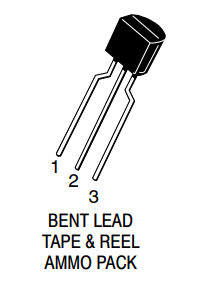
MOSFET, in short, is a metal oxide semiconductor field-effect transistor used to switch or amplify voltages in circuits. Being part of the field-effect transistor family, it is a current-controlled device that is constructed with 3 terminals;
- Source
- Gain
- Drain
The purpose of a MOSFET transistor is essentially to control voltage/current flow between the source and the drain. The working principle differs based on the type of MOSFET.
Working Principle of MOSFET
To understand how MOSFET transistors work, we’ll take a look at a typical circuit diagram as follows:
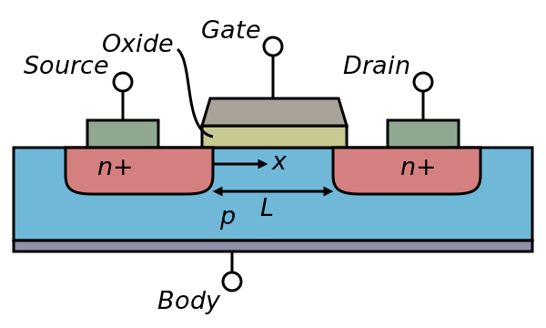
- A block, also known as a substrate of p-type semiconductor acts as the base for MOSFET
- Two sides on this p-type substrate are made highly doped with an n-type impurity (marked as n+)
- The drain terminals (Source and Drain) are then brought out from these two end regions
- The entire surface of the substrate is coated with a layer of silicon dioxide
- Silicon dioxide acts as insulation
- A thin insulated metallic plate is then placed on top of the silicon dioxide, acting as a capacitor plate
- The gate terminal is then brought out from the thin metallic plate
- A DC circuit is then formed by connecting a voltage source between these two n-type regions (marked in red)
When voltage is applied at the gate, it generates an electrical field that changes the width width of the channel region, where the electrons flow. The wider the channel region, the better conductivity of a device will be.
Types of MOSFET and Functions
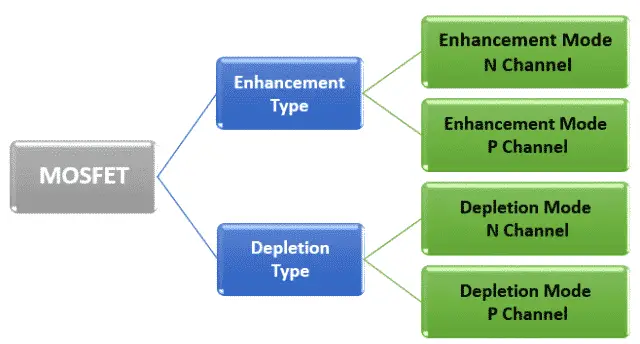
There are two classes of MOSFETS; Depletion Mode, and enhancement mode. Each class is available as n-channel or p-channel, tallying up to four types of MOSFETs in total!
Here are its explanation, alongside the working principle:
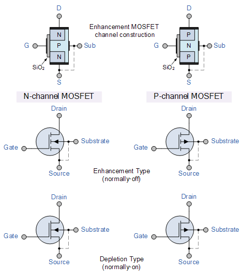
Depletion Mode:
- Depletion mode tends to be referred to as a normally closed switch
- It states that when there’s no voltage applied at the gate, channel conductance is at its maximum
- When voltage is applied at the gate, The conductivity of the device decreases
Enhancement Mode:
- Enhancement mode tends to be referred to as a normally open switch, where for conductance to occur, voltage is needed to pass-through
- When there’s no voltage applied at the gate, there’s no conductance
- When voltage is applied at the gate, the conductivity of the device increases
N-Channel MOSFET:
- The drain and the source are doped with n+ impurity while the substrate is in p-type
- The current flows through the P-channel MOSFET
- When a positive voltage is applied on the gate, the electrons from the n+ source and the drain region are attracted towards it, forming an electron reach channel
P-Channel MOSFET:
- Unlike the N-channel, the drain and the source are doped with p+ impurity while the substrate is in n-type
- The current flows through the P-channel MOSFET
- When a negative voltage is appleid on the gate, the electrons underneath the sulfur oxide respond to the flow of current and get pushed downwards into the substrate
To summarise what I’ve gone through earlier, here’s an illustration of the respective MOSFET transistor symbols with the working principle:
What is MOSFET used for?
Earlier, we know that MOSFET is used to switch or amplify voltages in circuits, however, what are some real-life applications?
- Auto intensity street light control
- Pairing with microcontroller to build a system that controls lights automatically through the respective clock pulses
- Radio-controlled applications such as boats, helicopters, and drones
- Motor torque and speed control
- Industrial control environments and robotics
Essentially, applications of the MOSFET can be found in various electrical and electronic projects that can be easily built nowadays with a microcontroller.
MOSFET vs BJT
So, now you’ve understood the basics of MOSFET and its working principle, what’s the difference between it over a regular transistor (also known as BJTs, bipolar junction transistor)?
Below summarises its differences in a table:
| MOSFET | BJT | |
|---|---|---|
| What it is | Metal oxide semiconductor field-effect transistor | Bipolar Junction Transistor |
| Hardware Construction | 3 terminals: Gate, source, drain with higher structure complexity | 3 terminals: Emitter, base, and collecter |
| Working Principle | For MOSFET to work, it’s dependent on the voltage at the oxide insulated gate electrode | For BJTs to work, it’s dependent on the current at the base terminal |
| Suitability of usage | High power, current control applications Analog and digital circuits |
Low-current applications |
Which transistor should you choose?
Although MOSFET holds advantages over BJT such as voltage control, choosing either comes down to your application purposes. Here’s what each transistor are suitable for:
- If you’re looking to regulate the flow of high current in narrow pulses, or for any high power applications, MOSFET is the way to go
- For common electrical circuit usages or low current in-home applications, BJTs may well be sufficient in handling the job
Using MOSFET with Arduino
Earlier, we’ve established that MOSFET is part of a FET family, making it a great option for large current flow control. But do you know it’s the first compact transistor that could be miniaturized for a wide range of usages?
Yes! with the revolution in electronics technology, it slowly made its way into miniaturized modules for microcontroller usages (E.g. Arduino)
Below we have a MOSFET transistor recommendation, perfect for such usage!
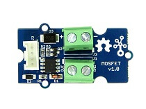
Grove – MOSFET

As its name suggests, the Grove – MOSFET is a miniaturized MOSFET transistor that helps you easily control a high voltage project with your Arduino board!
It features:
- Two screw terminals on board; one for outer power source, while the other for the device you want control over with
- 5V – 15V voltage control
Thanks to our Grove system as well, you’ll be able to experience plug and play through our Grove cables, easily adding or removing this transistor to your electronic project!
Interested to find out more about the Grove – MOSFET? You can visit its product page here for its datasheet, schematic, and more!
MOSFET Transistor Arduino Tutorial
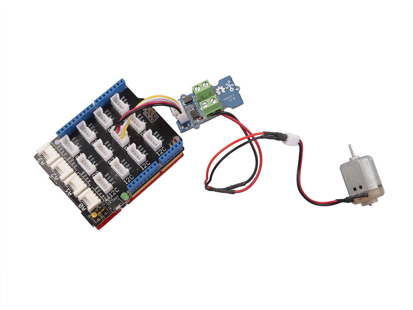
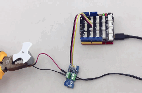
Now that we’ve introduced our very own MOSFET transistor module, let us guide you through how you can use it with your Arduino board!
For today’s tutorial, we’ll be demonstrating how you can use the Grove – MOSFET to control a motor. Power is provided through an external power source. However, if your controlled device needs a current smaller than 300mA, Seeeduino is supported without extra power!
Hardware components needed:
- Seeeduino is Seeed’s very own Arduino board, built with relative benefits over the original
- If you do not wish to purchase a Seeeduino, this tutorial is still applicable for the following Arduino boards: Arduino UNO, Arduino Mega, Arduino Leonardo, Arduino 101, Arduino Due
Hardware assembly:
- Step 1: Connect Grove – MOSFET to port D6 of Grove – Base Shield
- Step 2: Plug Grove – Base Shield into Seeeduino
- Step 3: Connect Seeeduino to PC via a USB cable
It should look something like this after the above steps:
Follow the pinout below if you’re planning on attaching actuators. This module accepts 5V – 15V power (less than 2A current) as well.
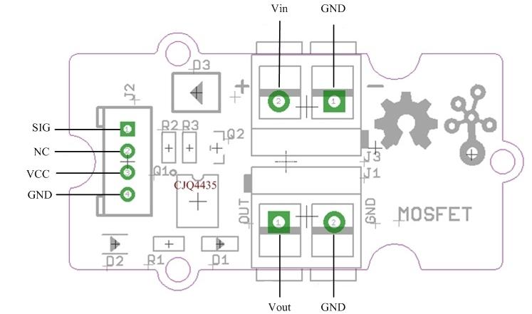
- Attach actuators on Vout
Software configurations and Arduino code
- Step 1: Copy the code below into Arduino IDE and upload it
- If you’re unsure on how to upload the code, do check our guide here
// demo of Grove - MOSFET
// use  pwm pin 6 to control a motor

int motorPin = 6;

void setup()
{
    Serial.begin(38400);
    pinMode(motorPin, OUTPUT);
    Serial.println("Grove - MOSFET Test Demo!");
}

void loop()
{
    motorOnThenOffWithSpeed();
    motorAcceleration();
}

void motorOnThenOffWithSpeed()
{
    int onSpeed  = 200;                         // a number between 0 (stopped) and 255 (full speed)
    int onTime   = 2500;
    int offSpeed = 50;                          // a number between 0 (stopped) and 255 (full speed)
    int offTime  = 1000;
    analogWrite(motorPin, onSpeed);
    delay(onTime);
    analogWrite(motorPin, offSpeed);
    delay(offTime);
}

void motorAcceleration()
{
    int delayTime = 50;
    for(int i=0; i<256; i++)
    {
        analogWrite(motorPin, i);
        delay(delayTime);
    }

    for(int i=255; i>=0; i--)
    {
        analogWrite(motorPin, i);
        delay(delayTime);
    }
}- Step 2: Now observe the state of the motor
Summary
That’s all for today’s guide on MOSFET and Arduino usage. I hope with this, you get a basic understanding of what is MOSFET, how it works, comparison with regular transistors and Arduino usage!
If you’re looking for easy Arduino interfacing with MOSFET, do consider our Grove – MOSFET!