How to use Water Flow Sensor / Meter with Arduino
Well, in this blog we will tell you basically all the things you need to know about the Water Flow Sensor, which including:
- A short description of the water flow sensor.
- The working principle of the hall water flow sensor.
- How to use a water flow sensor (Hardware and Code).
- The detail about the calculation formula.
What is a water flow sensor(meter)?
We use a water flow sensor to measure the water flow rate. The water flow rate is the volume of fluid that passes per unit time. People often use water flow sensor for automatic water heater control, DIY coffee machines, water vending machines, etc.
There are a variety of flow sensors of different principles, but for makers using Arduino or Raspberry Pi, the most common flow sensor is based on a Hall device. For example, the most classic water flow sensor YF-S402 and YF-S201 rely on Hall sensors.
So, how does the Hall water flow sensor work?
How does the water flow sensor work?
In order to explain how does the water flow work, let’s open the lid and take a look.
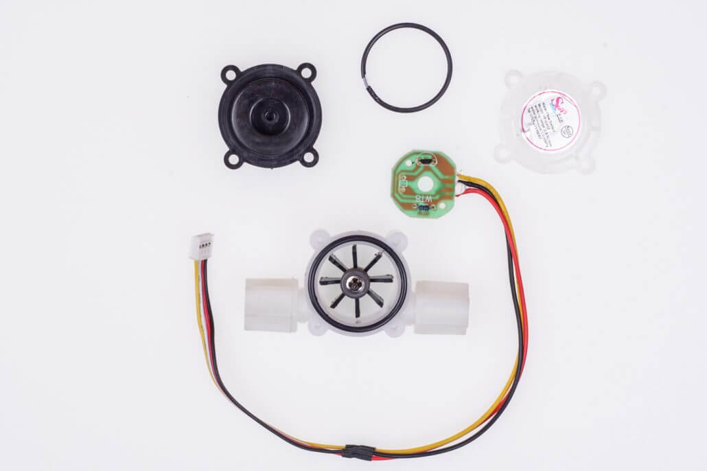
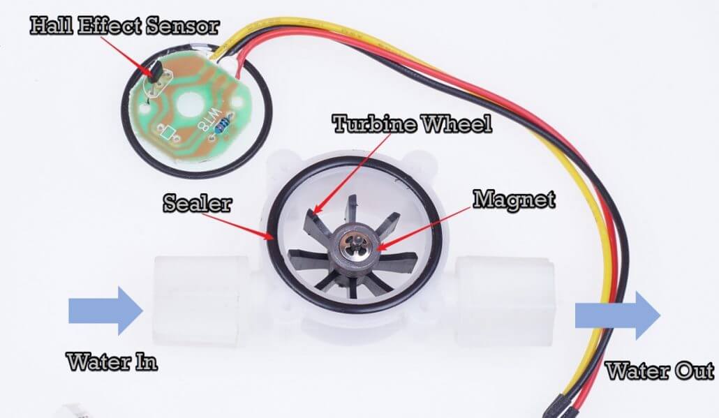
It’s quite simple inside. The main components are the Hall Effect sensor, turbine wheel, and magnet. The water flows in through the inlet and out through the outlet. The water current drove the wheel to turn, and the magnet on the wheel turned with it. Magnetic field rotation triggers the Hall sensor, which outputs high and low level square waves(pulse).
For every round of the wheel, the volume of water flowing through is a certain amount, as is the number of square waves output. Therefore, we can calculate the flow of water by counting the number of square waves(pulse).
How to use the water flow sensor with Arduino.
Material Required
Hardware Connection
For the YF serial, there are 3 wires:
- Red for Vcc
- Black for GND
- Yellow for pulse output.
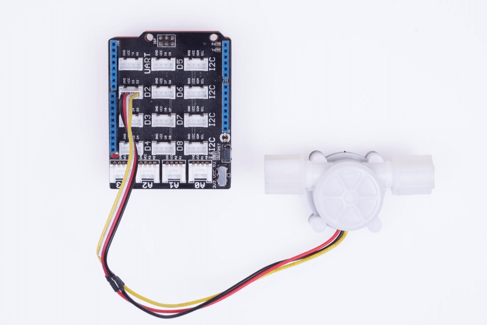
For the Atmega 328-based board like Arduino UNO and Seeeduino V4.2. There are two digital pins that can be used as an interrupt. Digital pin 2 for interrupt 0, and digital pin 3 for interrupt 1. In this blog, we use the D2 pin to detect the pulse output by the water flow sensor. If you are using Seeeduino + Grove base shield, just plug the water flow sensor to the D2 connecter. If you are using other Arduino board please use jumper cables to connect to the right pin.
Software Code
Of course, you can use digitalread() in the LOOP function to read the output of the water flow sensor. Count number plus one whenever a high level is read. However, this approach is not real-time, and the program requires a certain waiting time for each execution, during which new pulses are not detected.
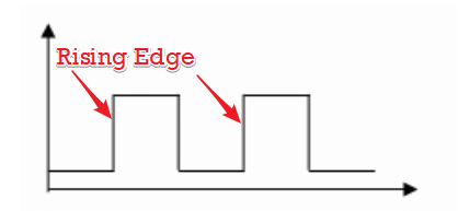
For such real-time demanding applications, we typically use interrupt. Whenever the rising edge of the pulse is detected, an interruption is triggered, counting plus one.
For more detail about interrupt please check attachinterrupt().
Then open your Arduino IDE and copy the code below. Download the code into Arduino.
Note:
The code here is for the most classic YF – S201 Water Flow Sensor. However the picture above is YF – S402. Beacause we do not have YF – S201 in our hand. The code used for both is almost the same, with only one factor to be modified.
/*
YF‐ S201 Water Flow Sensor
Water Flow Sensor output processed to read in litres/hour
Adaptation Courtesy: www.hobbytronics.co.uk
*/

volatile int flow_frequency; // Measures flow sensor pulsesunsigned

int l_hour; // Calculated litres/hour
unsigned char flowsensor = 2; // Sensor Input
unsigned long currentTime;
unsigned long cloopTime;

void flow () // Interrupt function

{
   flow_frequency++;
}

   void setup()
 {
   pinMode(flowsensor, INPUT);
   digitalWrite(flowsensor, HIGH); // Optional Internal Pull-Up
   Serial.begin(9600);
   attachInterrupt(0, flow, RISING); // Setup Interrupt
   sei(); // Enable interrupts
   currentTime = millis();
   cloopTime = currentTime;
}

   void loop ()
{
   currentTime = millis();
   // Every second, calculate and print litres/hour
   if(currentTime >= (cloopTime + 1000))
   {
      cloopTime = currentTime; // Updates cloopTime
      // Pulse frequency (Hz) = 7.5Q, Q is flow rate in L/min.
      l_hour = (flow_frequency * 60 / 7.5); // (Pulse frequency x 60 min) / 7.5Q = flowrate in L/hour
      flow_frequency = 0; // Reset Counter
      Serial.print(l_hour, DEC); // Print litres/hour
      Serial.println(" L/hour");
   }
}
Open the serial monitor tool and set the baud rate to 9600. as the water through, the flow value will print to the appropriate window.
The Formula for the calculation of water flow sensor
In the code section, we used the following formula, so how did this formula come about?
l_hour = (flow_frequency * 60 / 7.5)Earlier we mentioned that with each revolution of the wheel, the volume of fluid flowing through is certain. At the same time, the number of pulses generated per revolution of the wheel is also a certain amount. Thus, we can establish an equation between the number of pulses and the water flow.
In fact, the YF series uses a ring magnet with six alternating poles, so that for every revolution, three low levels and three high levels, i.e., three pulses, are generated.
For the YF-S201, every liter of water that flows, the Hall Sensor outputs 450 pulses. Let’s do little math here.
450 pulse for 1 liter, so each pulse means 1/450 liter water flowing through.
We take the total volume of liquid flowing through the water flow sensor at a certain time t(unit s) as V_total(unit L), and the total number of pulses detected as N. Then we get:
V_total(L) = N* 1/450(L) Also, the total volume of fluid flowing through the water flow sensor is equal to the water flow rate(Q - unit L/s) multiplied by time t(unit s) .
V_total(L) = Q(L/s)*t(s) So, we get:
N* 1/450 = Q(L/s)*t(s)
N/t = 450 * Q(L/s)
N/t happen to be frequency f, so:
f = 450*Q(L/s);
Q(L/s) = f/450;
Q(L/min) = f*60/450 = f/7.5
Q(L/hour) = f*60*60/450 = f*60 /7.5
For the YF – S402, every liter of water that flows, the Hall Sensor outputs 4380 pulses. So, the formula should be:
f = 4380*Q(L/s);
Q(L/s) = f/4380;
Q(L/min) = f*60/4380 = f/73
Q(L/hour) = f*60*60/4380 = f*60 /73
That’s all about this blog.
You can also check How to select the best water flow sensor for your project to help you find the right one.