The Basics of Filters and the Different Types of Filters
In the field of electronics, filters can be found in almost all electronic devices from audio circuits to radios and even to measuring devices, serving important roles resulting in its smooth operation. With a concept similar to a standard filter that you can find in an air-conditioning unit or water purifier, electronic filters allow signals within a certain frequency range to pass through, and signals outside that range to be filtered out or attenuated in this case. In addition, the frequency ranges of your filter circuits can certainly be adjusted easily based on what you are using it for by changing component values in these filter circuits and we will talk about further on. Today, we will mainly be discussing the difference between passive and active filters, the four main types of filters, and the basics of building a filter.
Passive vs Active Filters
The main difference between these two filter categories is that passive filters utilize passive components like resistors, capacitors, and inductors (which are quite basic components you can find to build a filter) whereas active filters utilize active components such as op-amps (operational amplifiers) alongside parts of a passive filter as well. In terms of the individual differences which separate these filters in its operation, one big aspect is that active filters do require an external power supply for it to work while passive filters simply just operate on its input signal. In addition, active filters do have frequency limitations due to the set components used whereas passive filters do not have any major limitations because of the fact that you can swap out components easily. Furthermore, due to passive components generally being used, passive filters do have better stability and are generally cheaper to build whereas active filters do cost a bit more, but can eliminate harmonics and has a power gain in the filtering of its input signal. Therefore, they both have their individual pros and cons which you may want to consider when using one of these filters for any future project.
The Four Main Types of Filters
Firstly, a low-pass filter, as the name says, attenuates frequencies higher than the set cutoff frequency and allows the frequencies lower than that to pass. We use the term ‘center frequency’ when referring to that bit of frequency space separating the upper and lower cutoff frequencies, depending on the filter of course. On the other hand, a high-pass filter is simply the opposite, where it attenuates frequencies below a certain cutoff frequency and allows frequencies higher to pass. We use the term ‘stopband frequency’ to define the frequency in which the attenuation of the signal starts with the rest of the frequencies in that bandwidth now known to be in the ‘stopband’.
Now that we’ve covered a bit on low-pass and high-pass filters, another type of filter is the band-pass filter. Simply said, a band-pass filter basically combines the likes of the two other filters as bandpass filters allow a certain range of signals with certain frequencies to pass, in its so-called passband, and attenuate all the other frequencies in its stopband. Lastly, I would personally describe this filter type as the inverse to a bandpass filter: the notch filter. Similar to the bandpass filter, a notch filter attenuates frequencies in a certain range only and allows the other frequencies surrounding it to pass (in its passband). The main difference between a bandpass and notch filter is that a bandpass filter allows signals within a particular frequency range to pass and a notch filter will filter those signals out in that one frequency range. Refer to the below diagram for a visual on how the different types of filters work:
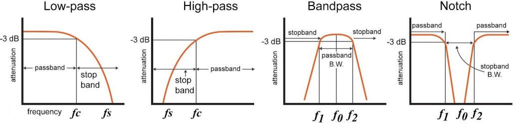
Image credits go to All About Circuits.
In terms of the applications for filters, it’s endless and one use for these filters which I am quite familiar with is for radios. Providing decent selectivity for a radio receiver is extremely important to its operation and can help the operator greatly, as many radios have a wide receive bandwidth and with a decent filtering circuitry, it can help to really extract signals on certain frequencies as well as weak signals which you want to pick up clearer.
Building a Filter
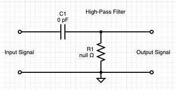
Today, the basics of building a simple passive filter will be explained, relying only on the simplest of components of whatever values you have available lying around. We will not be building an active filter today as it uses different components that you may not have available and is slightly more complex, but the basics of filters always trace back to a passive filter. The main two components which you will need are simply a resistor and a capacitor (non-polarized is preferred for simplicity). They will be placed in series where your input signal will be fed through the capacitor, into the resistor, and back to ground. This configuration actually makes a high-pass filter but if you place the resistor first in the circuit and then the capacitor going to ground, you will create a low-pass filter. With these circuits, you can measure your output signal in between the resistor and capacitor with an oscilloscope where you will notice whether your signal is attenuated or not depending on your input signal frequency and the filter components.
To calculate the cutoff frequency in which your input signal will be filtered out, we can use this equation:

where R represents your resistor’s resistance value in ohms and C represents the capacitor’s capacitance value in farads. This will then give you a frequency result in Hz, which will help you to identify what your cutoff frequency will be for your filter circuit. In order to change this cutoff frequency for your filter, experiment around with different resistor and capacitor values, and be sure to use the equation to suit your desired application. With that said, there can be many complex filter circuits that you can base off this simple design in many projects, whether you are making your own FM transmitter, a power supply unit, or an audio amplifier, and hopefully, this short article taught you something about filters which you can add on to later!
About Seeed Fusion
Seeed Fusion specializes in affordable but professional PCB manufacture and full turnkey PCB Assembly services to fit any budget. With over 10 years of experience in full-scale paper-to-product manufacturing, worldwide sourcing and supply chain management, Seeed Fusion takes the hassle out of realizing your design. Seeed Fusion PCBA service offers an unrivalled instant online quotation platform that obtains live pricing from the likes of DigiKey and Mouser, just upload the formatted BOM file for a full quotation in seconds. Plus, by choosing all parts from the Open Parts Libraries (OPL), a catalogue of over 20,000 parts local parts, you can reduce the PCBA production time to just 7 working days. The service is also packed with value-added services and options, including the signature Design for Assembly (DFA) review, whereby Seeed’s own electronic engineers provide their expertise to help you avoid costly pitfalls that could make or break a project. Get an instant online quote now.