Seeed Grove Designers’ Guide: PCB design guidelines and more
The Seeed Grove modular plug-and-play system currently consists of over 400 actuators and sensors developed over the course of 14 years. As Seeed’s debut series, the Grove ecosystem and ethos have evolved and continue to remain a leader in modular electronics, whether for education, hobbyist electronics or prototyping the next big product.
With so many Grove modules, it can be difficult not to find a sensor to measure a specific parameter, but with the rising demand for advanced, cheaper and more accurate sensors, and no shortage of manufacturers answering to that demand, there is plenty of room to improve on existing technology and cater to more advanced needs.
This is where the Develop Your Grove Sensor campaign from Seeed comes in, sponsoring designers to develop their own Grove modules and eventually make them available via Seeed channels. Whether to utilize new technology or to serve a niche field, designers can use their unique insight to come up with and co-develop Grove modules that like-minded users desire.
So how should creators go about designing a Grove module? What qualifies as a Grove module and what should designers look out for? This article sets out to give guidance to PCB designers and more.
What is Grove?
The Grove system consists of open-source, plug-and-play hardware for modular electronics project building. The system helps accelerate electronics project building by doing away with jumper wires and breadboards so engineers can focus on developing solutions and coding. This is achieved by providing standardized modules, connectors and cables to be used with Grove-compatible development boards and shields. The Grove family consists of a vast variety of modules, each with a single function, with freely available libraries and examples. Plus, with everything open-sourced, designers can easily import them into their product designs.
Types of Grove Modules
Grove modules can be grouped into sensors (input) and actuators (output). Sensor modules are the most varied, obtaining signals to be processed and actuators produce a physical response as a result of an input or process.
Environmental Sensors:
Sensors that measure air quality, soil moisture, temperature and humidity, atmospheric pressure (barometers), light intensity, sound etc.
Movement/Distance Sensors:
Sensors for measuring distance, speed, acceleration, gyroscopes etc.
Biosensors:
Sensors that detect body activity and biometrics such as fingerprint sensors, GSR, EMG, and heart rate sensors.
Communication Modules:
Modules that receive communication signals either wirelessly or via physical interfaces such as Wifi, BLE, GPS, LoRaWAN, NFC, RF, CAN, etc.
Human interfaces:
Modules for registering manual inputs such as buttons and switches, touchscreens and mics.
Actuators:
Modules for outputting responses such as buttons, switches and LEDs, LCD displays, motors, relays, speakers and buzzers.
What qualifies as a Grove Module?
There are certain traits that make the Grove modules that we know and love. Of course, there are exceptions but a few fundamental rules make the prototyping toolbox work.
Grove modules typically serve one function
A Grove module is not a development board. Grove modules typically feature a single main component; a sensor, a chip, an LED, button, potentiometer etc. with some additional basic hardware. Similar sensors can be grouped together if they perform a collective function such as the multi-gas sensor, which has 4 separate chips for sensing different gases.
They contain the minimal amount of circuitry to allow the main component to be used in a modular, plug-and-play fashion, receiving power and transferring signals via the 4-pin Grove interface to an external controller. If a control chip is required to operate the sensor then this can also be included on the module too, but we should not be seeing micro-controllers on the modules.
Grove modules connect via Grove interfaces
Grove modules have a female 4-pin Grove connector to connect to Grove cables. Power and data signals transmit primarily via the 4-pin Grove interface. The 3rd and 4th pins (red and black respectively) are for VCC and ground connections and the other two are for data transmission, depending on the type of Grove interface. Other interfaces are allowed to connect probes and additional hardware necessary to use the device.
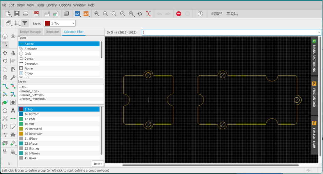
Grove module PCB boards come in standard Grove shapes
There are 5 standard Grove sizes, the most common being the square 20 x 20mm single unit and rectangular 20 x 40mm double unit. Each shape has the iconic interlocking Grove ‘rings’ and ‘sockets’ on the edges, perfect for screwing into enclosures. The single and double-unit shapes are large enough for most Grove module designs.
You can download a template for the single and double unit boards for Eagle here!
All Seeed Grove modules PCBs come in turquoise-blue color!
While there is no impact on functionality, we think the color is nice and is the signature color for Seeed Grove modules.
Which Grove Connector Should I use?
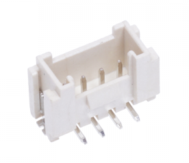
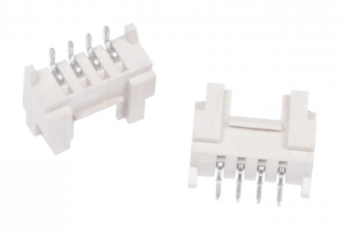
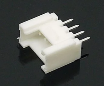
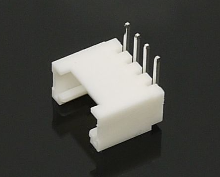
Grove boards need at least one female Grove connector (header). There are 4 different female Grove connectors: two for surface mounting and through-hole mounting, each with straight and right-angle configurations. All connect to Grove cables but which one you choose will depend mainly on how the board will be used and how the parts will be soldered.
Through–hole or surface mount?
The choice of mounting type depends on many factors. Through-hole parts are great for hand soldering prototypes or for applications where the connection needs to be more rugged, but when it comes to batch production, having a single through-hole part on a board where everything else can be surface mounted is a waste and could incur unnecessary costs. The table below compares some factors that may affect your decision.
| Surface Mount | Through-hole | |||
| Straight | Right-Angle | Straight | Right-Angle | |
| Hand soldering | Difficult | Difficult | Easy | Easy |
| Batch assembly* | Suitable | Suitable | Not suitable | Not suitable |
| Footprint size | Smallest single-side only footprint | Single-side only footprint | Smallest single-side footprint but on both sides | Footprint on both sides |
| Bond strength | Surface attachment only | Surface attachment only, wider surface area | Through boards | Through boards |
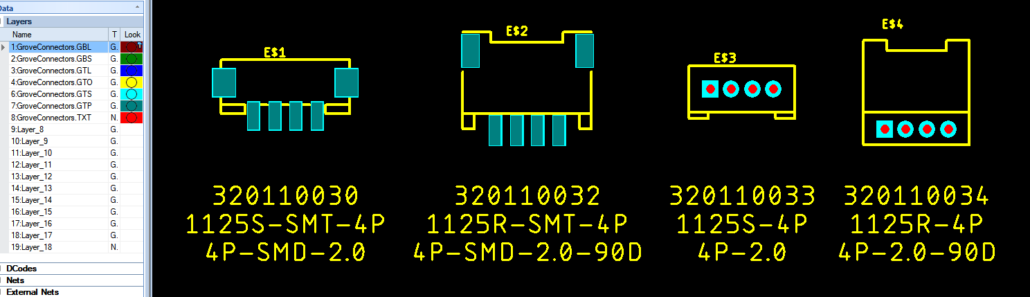
| SKU | 320110030 | 320110032 | 320110033 | 320110034 |
*referring to common batch-assembly methods such as pick and place and reflow soldering.
Once you are settled on an attachment type, consider how the cable will protrude from the Grove module and how this will affect how the board is used.
Take the capacitive moisture sensor as an example, one end of the board is designed to be inserted into the ground. The cable parallel to the board makes it easier to insert. Single and double-unit boards are more suited to use straight versions to maximize space on the boards for other parts. The main sensing/actuator part is often placed on the same side as the Grove connector for convenience when prototyping, unless orientation may impact its usage, for example, radars, lasers, and ultrasonic beams.
Take note of the placement of the connectors on the Grove modules as well. The connectors are fully enclosed by the outline and should not be hanging over the edge of the PCB in most cases. Detailed mechanical information can be found here.
How to include the Grove connector in the Bill of Materials (BOM) file?
Rather confusingly, there are multiple part numbers and SKU numbers for the four Grove configurations and multiple sources of information. The following table collates this information and should help make things clearer. Notice that the S in the part number is short for ‘straight’ but means perpendicular to the board, and the R is short for ‘right-angle’, but the connector is parallel to the board.
| Seeed SKU | Part Number (MPN) | Cost (USD) | Seeed Multi-pack SKU | Multi-pack link |
| 320110030 | 1125S-SMT-4P | 0.061 | 114020163 | Grove Female Header – SMD-4P-2.0mm-20Pcs |
| 320110032 | 1125R-SMT-4P | 0.042 | 114020164 | Grove Female Header – SMD-4P-2.0mm-90D-20Pcs |
| 320110033 | 1125S-4P | 0.01 | 110990030 | Grove Female Header – DIP-4P-2.0mm-10 Pcs |
| 320110034 | 1125R-4P | 0.01 | 110990037 | Grove Female Header – DIP-4P-2.0mm-90D-10 Pcs |
For manufacture with Seeed Fusion PCB Assembly service, the connectors are conveniently available in the Seeed Open Parts Library. Add the SKU beginning with 3, or the part number to the BOM file as you would for other parts.
The Seeed website also sells these connectors in small packs and reels. Please do not use these SKUs for your BOM file as the BOM file is supposed to contain all the parts for one board. If you use these parts, you could end up buying much more than you need and they are not packaged in a format suitable for batch assembly.
The Eagle and KiCad footprints for these connectors are available on GitHub, please use these for the best compatibility. Other similar connectors may be missing pads or may be slightly different in size.
PCB Layout Tips
A neat PCB layout makes a more attractive product and may have an impact on longevity too. Since Grove boards do not have enclosures and are designed to be manhandled by grubby fingers, aesthetics matter. These tips do not just apply to Grove boards, the reasoning can be applied to any board design! Other tips relate to the Grove series and help make your boards fit in with the Grove family.
Due to the limited space available, one of the biggest concerns with Grove boards is trying to fit everything in without looking too cluttered, while at the same time, making sure everything is placed conveniently for the user.
- Go small: For all your parts, you should try to find small surface mount packages where possible. Through-hole parts take up a lot of space on both sides of the boards so eliminate these as much as possible. Using small chip resistors, capacitors, LEDs for example is an easy way to make room without compromising functionality. But don’t go too small! 0201 may require more specialized equipment to ensure accurate placement. For Grove boards 0402 and 0603 sizes should leave plenty of room for other parts. If not, consider a larger Grove size.
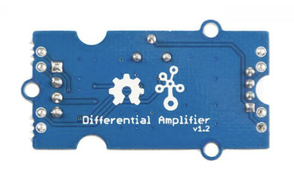
- Put text and logos on the bottom: For boards with parts only on one side, make use of the empty space and place all silkscreen text, logos and the product name on the bottom (side with less parts). Most Grove modules are single-sided and so have room for text and logos on the bottom.
- Remove silkscreen designators as a last resort: With crowded boards, there may not be enough room for the part designators, the labels in the silkscreen (R1, R2 etc.) and other silkscreen features. These are important for assembly and for users to recognize the parts if needed but if the boards are so crowded that the silkscreen would be unclear then delete them. But be sure to include a document informing the assembly house how to assemble your boards, along with polarity markers, etc..
- Use smaller vias: Vias also take up space! 0.3mm diameter vias are sufficient and will also mean the vias will be tented and therefore protected from dust and water damage.
- Maintain a clearance of at least 0.5mm around the edge of the boards: From any traces, pads, pour and silkscreen, and more if possible to protect parts from milling tools and frequent handling.
- Use copper pour: Fill any unused space with copper pour. Not only will you be using less chemical etchant during production, you also help bring out the brighter, non-translucent Grove blue color.
- Text should go with the flow: For longer Grove boards, the text should be orientated with the longer side of the boards e.g. Grove – Capacitive Sensor. That way you be able to fit the text in better without looking too crowded, especially modules with long names.
- Font should be similar to the default Eagle font: All Seeed Grove modules are designed in Eagle and use the default vector font with a height of 50 mils (or 1.27mm) for the module name. Other texts have a height of 32mils or 0.8128mm. Feel free to include your own logos and signature but..

- Do not include the Open Hardware logo: Designs must follow specific conditions to be able to use the Open Source Hardware logo in your design. Grove modules via the Develop Your Own Grove Sensor campaign are not restricted by such conditions and more than likely do not fulfill the definition stipulated by the OSHWA. Unless specifically made the effort to follow each condition, please do not use the logo in your design.
- Do not include the Seeed Studio logo: Doing so would suggest that we (Seeed Studio) made and maintain the design and documentation. You can add your own attribution if you wish and the Grove logo.
- Be neat: It should go without saying, but if your boards are approved for batch production and sale, your boards should be as aesthetically pleasing as possible. All silkscreen text should be clearly visible and placed next to the corresponding part and parts and labels should be centered and aligned where appropriate. Then, leave the rest to us and we will make sure your design is made to our own high-quality standards.
- Use Eagle: We know not everyone has or wants to use Autodesk Eagle but since all Seeed Grove boards are designed in Eagle, we have an Eagle .brd template available with the outline that our own engineers use. The template includes the board outline for single and double units, exact guides on where to place the connector, copper clearances, ideal test point locations, and part clearances so that your module is as much like a Grove module as possible and will be compatible with Seeed approved Grove accessories and enclosures. If you are on the fence about which design software to use then we definitely recommend Eagle first, because of the template and connector libraries. We also have libraries for KiCad but no template.
Eagle and KiCad footprint libraries
Tips to Reduce Costs
Low cost will help get your boards into the hands of more tinkerers. Grove boards are designed to keep costs down as much as possible (without compromising on quality). Many strategies can be employed at the design stage that don’t cost an arm and a leg.
- Maintain single-sided assembly as much as possible: When it comes to mass production, keeping surface mount components on one side will help reduce labor and production costs. For double-sided assembly, the boards have to go through the assembly line twice (that means solder-pasting, pick and place, reflow oven etc. x2!). Some assembly facilities charge extra for this, and it may introduce complications in the assembly process. For example, large parts may require glue or specially designed trays to keep them from falling during the second reflow.
- Do away with optional parts: It’s nice to consider every possible use case, but if it adds a few extra dollars to the final product, it could put off users especially if they will not likely use the feature. For example, instead of including a header for shorts or other connections, consider including pads that can be shorted with a tool or drop of solder, or just make the plated holes/pads available for users to solder additional parts onto.
- Use the Open Parts Libraries (OPL): Seeed has a catalog of parts locally available in the form of the Seeed and Shenzhen Open Parts Libraries that are used with the Seeed Fusion PCBA service. The Shenzhen OPL contains parts from local distributors often at a cheaper price, and the Seeed OPL contains parts from Seeed’s own warehouse, which includes parts used in Seeed’s Grove modules and development boards. Using parts in the OPL can both speed up delivery and cut BOM costs.
FAQ
Do I have to use the Grove connector?
Yes, the Grove connector is a semi-proprietary connector that is slightly different to JST standard connectors and clones. Grove connectors have an additional latching mechanism to help hold Grove projects together.
Do I have to include the Seeed logo on the boards?
No, in fact most Seeed Grove modules do not have the Seeed logo on them. They have the Grove logo instead, which you may add if you wish.
Do I have to use Autodesk Eagle to design the PCB?
No, all Seeed Grove boards are drawn using Eagle but we won’t force designers to use Eagle if they don’t want to. We just ask that they look similar to modules in the Grove family and there are more resources available for Eagle.
Missed anything? Let us know in the comments or get in touch. Happy designing!