ESP-IDF Pages and Peripherals
The first guide introduced the Sticky project structure and showed how data reaches a page through AppState. This guide continues with the same Comprehensive Development Demo (Sticky_dashboard_demo) and uses real peripherals to show when data is read, how input triggers application behavior, and how results are displayed on the e-paper screen.
This guide covers:
- Distinguish between data peripherals and input peripherals
- Reuse shared buses and power resources managed by the Board layer
- Combine multiple hardware states on one page
- Load page content from MicroSD
- Update pages through background events and user actions
- Choose between reading on page entry, background monitoring, and on-demand capture for different use cases
Before you begin, complete ESP-IDF Development Basics and confirm that the Demo can be built, flashed, and used to switch pages.
This guide uses the Device modules already included in the Demo to explain how to access peripherals and integrate them into a Sticky application. It does not cover chip registers or low-level driver development. To support new hardware, follow the interface patterns of the existing modules under main/devices/.
Peripheral Integration
Different peripherals produce data in different ways and at different times. The Demo groups them into the following integration patterns based on their actual use:
| Integration pattern | Example in the Demo | How it is used |
|---|---|---|
| Update on page change or refresh | SHT40, Battery, Charger | The App layer reads the data when the corresponding page opens or is manually refreshed |
| Load file content | MicroSD | Mount, read, and unmount when content is needed |
| Monitor state in the background | IMU | Detect stable state changes in the background and post an event |
| Capture on user request | Microphone | Capture one sample after an explicit user action |
| Input event | Button, Touch | Convert button or touch actions into AppEvent |
Data peripherals follow the path introduced in the first guide:
Device -> app_data -> AppState -> Page -> Canvas -> Display
Input peripherals do not provide display data to a page. Instead, they trigger application behavior:
Button / Touch -> AppEvent -> handle_app_event() -> Page / Display
The following sections use Button, Touch, Battery, MicroSD, IMU, and Microphone to show how each integration pattern works. When developing a feature, first identify when its data is produced, then choose the closest pattern.
Reuse Board-layer resources
Some Sticky peripherals share communication buses, and peripheral power is controlled by software as needed. board_init() keeps the system powered, sets the default MicroSD state, and creates the shared sensor I2C bus. Each Device module then reuses these resources during initialization.
The main resource relationships in the Demo are:
| Resource | Peripheral | Management |
|---|---|---|
| I2C1, GPIO0/GPIO1 | BQ27220, PCF8563, SHT40, LSM6DS3TR-C | Reuse board_sensor_i2c_bus() |
| I2C0, GPIO2/GPIO3 | GT911 Touch | Created separately by sticky_touch |
| SPI2 signal lines | E-paper, MicroSD | Use different CS pins and share the same SPI2 Host |
| Peripheral power | E-paper, Touch, MicroSD, Microphone | Controlled by the corresponding module according to its active state |
board_init() creates the sensor I2C bus only once:
i2c_master_bus_config_t sensor_bus_config = {};
sensor_bus_config.i2c_port = I2C_NUM_1;
sensor_bus_config.sda_io_num = static_cast<gpio_num_t>(PIN_SENSOR_SDA);
sensor_bus_config.scl_io_num = static_cast<gpio_num_t>(PIN_SENSOR_SCL);
sensor_bus_config.clk_source = I2C_CLK_SRC_DEFAULT;
sensor_bus_config.glitch_ignore_cnt = 7;
sensor_bus_config.flags.enable_internal_pullup = 1;
result = i2c_new_master_bus(&sensor_bus_config, &s_sensor_i2c_bus);
Device modules that need the sensor bus reuse the same I2C bus handle:
ESP_ERROR_CHECK(sticky_battery_init(board_sensor_i2c_bus()));
ESP_ERROR_CHECK(sticky_sht40_init(board_sensor_i2c_bus()));
ESP_ERROR_CHECK(sticky_rtc_init(board_sensor_i2c_bus()));
ESP_ERROR_CHECK(sticky_imu_init(board_sensor_i2c_bus()));
Before developing a feature, check whether the existing Board and Device modules already provide the required resources. Do not create buses in a page, and do not create a separate I2C bus for each sensor on GPIO0/GPIO1.
If an I2C peripheral fails to initialize, first confirm that board_init() has completed and check whether the peripheral reuses board_sensor_i2c_bus(). Creating multiple I2C buses on the same pins usually causes resource conflicts.
Button and Touch Interaction
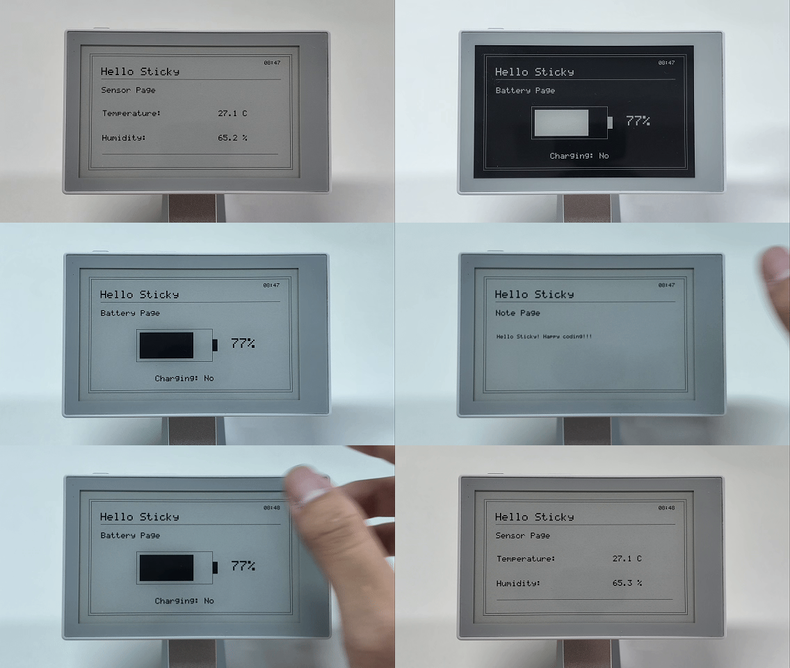
The Hello page created in the first guide does not need separate button or touch handling. Once the page is included in the navigation order, the existing input modules can switch to it through the shared events.
The Demo maps inputs to these events:
| Input | AppEvent | Application behavior |
|---|---|---|
| Short press UP | PreviousPage | Go to the previous page |
| Short press DOWN | NextPage | Go to the next page |
| Swipe right | PreviousPage | Go to the previous page |
| Swipe left | NextPage | Go to the next page |
| Short press AI | RefreshPage | Read and refresh the current page again |
| Hold AI for about two seconds | EnterDeepSleep | Enter Deep Sleep, covered in the third guide |
Button events
sticky_buttons_init() registers the three buttons with the existing events:
esp_err_t result = create_button(
    PIN_BTN_UP, AppEvent::PreviousPage, &s_up_button);
if (result != ESP_OK) {
    return result;
}
result = create_button(
    PIN_BTN_DOWN, AppEvent::NextPage, &s_down_button);
if (result != ESP_OK) {
    return result;
}
return create_button(PIN_BTN_OK,
                     AppEvent::RefreshPage,
                     &s_refresh_button,
                     true,
                     AppEvent::EnterDeepSleep);
The button callback only places an event in the queue:
void button_click_callback(void *button_handle, void *user_data)
{
    (void)button_handle;
    const auto event = static_cast<AppEvent>(
        reinterpret_cast<uintptr_t>(user_data));
    app_event_post(event);
}
Touch events
GT911 coordinate conversion is handled inside sticky_touch. After the finger is released, the module only checks whether the gesture forms a clear horizontal swipe:
if (horizontal_distance < kMinimumSwipeDistance ||
    horizontal_distance <= vertical_distance * 2) {
    return false;
}

event = delta_x < 0 ? AppEvent::NextPage : AppEvent::PreviousPage;
return true;
The horizontal movement must be at least 120 logical pixels and greater than twice the vertical movement. Taps, short movements, and mainly vertical gestures do not trigger a page change.
Application event handling
The main loop takes events from the queue and passes all of them to handle_app_event():
while (true) {
    AppEvent event;
    if (!app_event_wait(event, portMAX_DELAY)) {
        continue;
    }

    const esp_err_t result = handle_app_event(*canvas, state, event);
    if (result != ESP_OK) {
        ESP_LOGE(kTag, "App event failed: %s", esp_err_to_name(result));
    }
}
The App layer changes PageId, updates page data, calls the Renderer, and refreshes the screen. After a page change or manual refresh, it calls sticky_buzzer_beep() to provide audio feedback. Neither the input modules nor the pages control this flow directly.
Data Reading and Display
This section uses the Battery and Note pages to introduce two data integration patterns. Battery combines several hardware states on one page, while Note loads external file content from MicroSD.
Battery and charging state
The Sensor page in the first guide mainly displayed data from a single sensor. The Battery page shows how to combine two hardware results in one state:
BQ27220 -> Battery percent ─┐
                            ├-> AppState.battery -> Battery Page
External power -> Charging ─┘
The related code is located in:
main/devices/sticky_battery.*
main/devices/sticky_charger.*
main/app/app_state.h
main/app/app_data.cpp
main/pages/battery_page.*
Update battery state
BatteryState records the validity of the battery level and charging state separately:
struct BatteryState {
    int percent = 0;
    bool valid = false;
    esp_err_t error = ESP_ERR_INVALID_STATE;
    bool charging = false;
    bool charging_valid = false;
    esp_err_t charging_error = ESP_ERR_INVALID_STATE;
};
update_battery() reads the BQ27220 and external power state in sequence:
void update_battery(AppState &state)
{
    BatteryReading reading = {};
    const esp_err_t battery_result = sticky_battery_read(reading);
    state.battery.error = battery_result;
    state.battery.valid = battery_result == ESP_OK;
    if (battery_result == ESP_OK) {
        state.battery.percent = reading.percent;
    }

    bool charging = false;
    const esp_err_t charger_result = sticky_charger_read(charging);
    state.battery.charging_error = charger_result;
    state.battery.charging_valid = charger_result == ESP_OK;
    if (charger_result == ESP_OK) {
        state.battery.charging = charging;
    }
}
The two results are stored independently. Even if the battery gauge read fails, the page can still display the external power state, and vice versa.
Display battery status
The Battery page calculates the battery bar width when the data is valid. Otherwise, it keeps the empty battery outline:
if (state.battery.valid) {
    const int inner_width = battery_width - padding * 2;
    const int fill_width = inner_width * state.battery.percent / 100;
    canvas.fill_rect(battery_x + padding,
                     battery_y + padding,
                     fill_width,
                     battery_height - padding * 2,
                     GrayLevel::Black);
}
After connecting or disconnecting USB-C, open the Battery page again or short-press AI so the App layer calls update_battery() again.
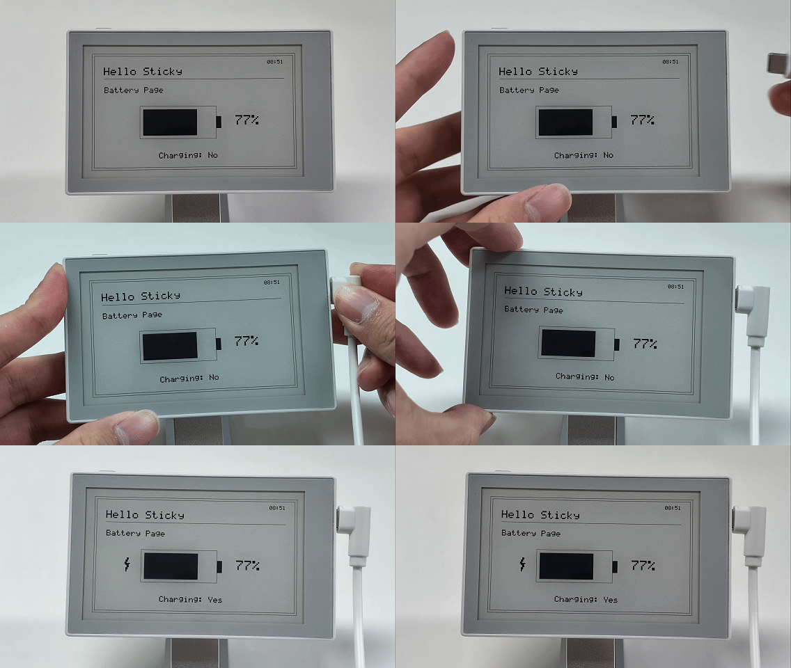
When a page combines several data sources, you can follow the same structure. Examples include displaying indoor and outdoor temperatures with network state and update time, or summarizing results from multiple sensors.
Read files from MicroSD
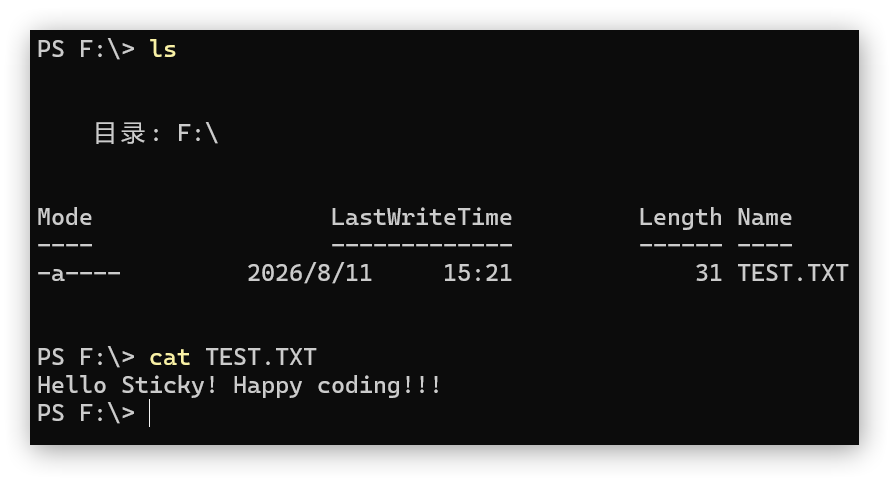
The Note page shows how to integrate file-based data. It reads TEST.TXT from the root directory of the MicroSD card, then passes the content to the page through AppState.note:
MicroSD / TEST.TXT
-> sticky_sdcard_read_text()
-> AppState.note
-> Note Page
Prepare the text file
- Format the MicroSD card with a compatible FAT file system.
- Create
TEST.TXTin the root directory of the card. - Add plain text for testing and save the file.
- Insert the MicroSD card into Sticky.
For example:
Hello Sticky! Happy coding!!!
NoteState stores up to 256 bytes of text. The current page draws up to 6 lines and processes up to 52 single-byte characters per line. The Demo renders text one byte at a time, so use short English text, numbers, and symbols for the first test.
SPI2 resource sharing
update_note() only calls the Device API and stores the result:
void update_note(AppState &state)
{
    const esp_err_t result = sticky_sdcard_read_text(
        "TEST.TXT", state.note.text, sizeof(state.note.text));
    state.note.error = result;
    state.note.valid = result == ESP_OK;
    if (result != ESP_OK) {
        ESP_LOGW(kTag, "Note load failed: %s", esp_err_to_name(result));
    }
}
In the Demo, the e-paper display and MicroSD use the same SPI2 signal lines with different CS pins. To avoid resource contention, sticky_sdcard_read_text() completes the file read and unmount operation before the App layer refreshes the display:
Detect the card
-> Enable MicroSD power
-> Mount the file system
-> Read TEST.TXT
-> Unmount the file system
-> Release shared SPI2 access
-> Render and refresh the e-paper display
The App layer renders the Note page only after the read has finished:
} else if (state.current_page == PageId::Note) {
    // SD is unmounted before render_current_page() refreshes the display.
    update_note(state);
}
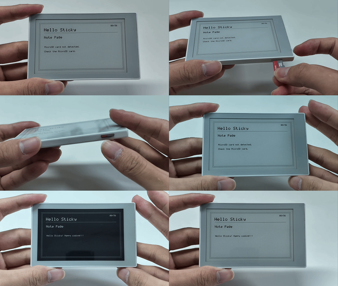
Opening the Note page or short-pressing AI on that page reads the file again. If the card is missing, the mount fails, or the file does not exist, the page prompts you to check the MicroSD card while the other pages remain available.
State Monitoring and Data Capture
IMU and Microphone data are not read directly every time their pages open. The IMU monitors stable orientation changes in the background, while the Microphone waits for an explicit user action before capturing one sample.
| Pattern | Example | Update timing | Trigger mechanism |
|---|---|---|---|
| Background state monitoring | IMU | When the stable orientation changes | OrientationChanged |
| User-triggered capture | Microphone | When AI is short-pressed on the Microphone page | RefreshPage |
IMU state monitoring
Battery and Note are read when their page content is needed. The IMU instead monitors device orientation continuously and only notifies the App when the stable orientation changes:
IMU monitoring task
-> stable orientation changed
-> AppEvent::OrientationChanged
-> update_imu()
-> IMU Page
After initialization, main.cpp starts the IMU monitoring task:
ESP_ERROR_CHECK(sticky_imu_start_monitoring());
The monitoring task reads acceleration every 100 ms. It treats an orientation as stable and posts an event only after the same orientation appears 5 times in a row:
if (candidate_count >= kStableSampleCount && candidate != stable) {
    stable = candidate;
    sample.orientation = stable;
    store_state(sample);
    app_event_post(AppEvent::OrientationChanged);
} else {
    sample.orientation = stable;
    store_state(sample);
}
This stability check reduces frequent page refreshes caused by small movements.
IMU page updates
When the App layer receives an orientation change event, it first checks the current page:
if (orientation_event && state.current_page != PageId::Imu) {
    return ESP_OK;
}
It reads the latest stable state and refreshes the screen only while the IMU page is visible. Other pages are not repeatedly refreshed by background orientation changes.
update_imu() gets the latest stored state from the Device module:
StickyImuState reading = {};
const esp_err_t result = sticky_imu_get_state(reading);
state.imu.error = result;
state.imu.valid = result == ESP_OK;
if (result == ESP_OK) {
    state.imu.orientation = reading.orientation;
}
The IMU page draws an arrow for the detected orientation. If the device is lying flat or the direction is not stable yet, the page asks you to hold it upright. Background orientation events do not play the buzzer, which avoids repeated sounds from normal device movement.
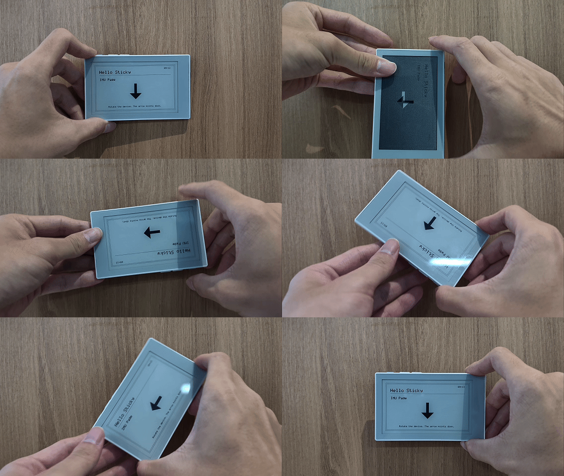
For a feature that needs continuous monitoring but should update the UI only when its state changes, use the same event pattern. Examples include a door sensor state, threshold alert, or external interrupt event.
Read microphone data
Microphone capture does not need to run continuously. The Demo captures about one second of audio only when AI is short-pressed on the Microphone page:
AI short press
-> AppEvent::RefreshPage
-> sticky_microphone_capture()
-> AppState.microphone
-> Microphone Page
The first time the Microphone page opens, it does not capture automatically. The screen displays:
Press AI button to sample
The App layer checks both the current page and the event type:
} else if (state.current_page == PageId::Microphone &&
           event == AppEvent::RefreshPage) {
    update_microphone(state);
}
update_microphone() records whether capture was attempted, whether it succeeded, and the RMS, Peak, and volume percentage. The following code highlights the capture result state:
MicrophoneReading reading = {};
const esp_err_t result = sticky_microphone_capture(reading);
state.microphone.captured = true;
state.microphone.error = result;
state.microphone.valid = result == ESP_OK;
After a successful read, the complete implementation also writes the RMS, Peak, and volume percentage from reading into AppState.
The Device module enables microphone power and the PDM receive channel when capture begins, then disables them immediately afterward. The page draws the volume bar, RMS, and Peak from the result, or shows an error message if capture fails.
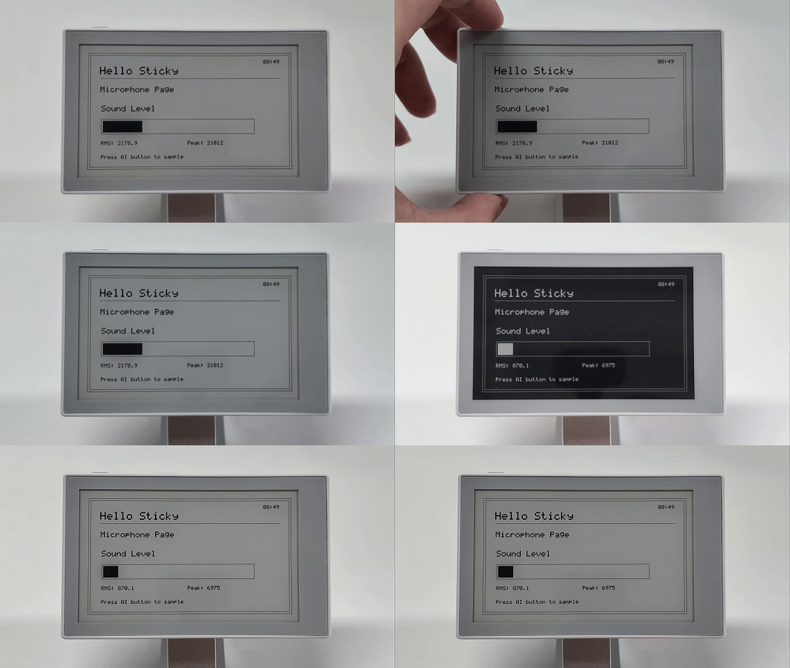
For features such as the microphone that only need to run after a user action, use on-demand capture. When adding a similar feature, let the App layer check the current page and trigger event before calling the corresponding Device API. The page Renderer still only displays the result.
Feature Verification
Build and flash Sticky_dashboard_demo again:
idf.py build
idf.py -p PORT flash monitor
Verify the following on Sticky:
- UP/DOWN and left/right swipes use the same page order
- A short press of AI reads and refreshes the current page again
- The Battery page displays the battery level and external power state separately
- The Note page reads
TEST.TXTand can reload it after the file changes - The IMU page updates its arrow only after a stable orientation change
- The Microphone page captures only after a short press of AI
- If one peripheral read fails, the other pages remain available
The five integration patterns above are coordinated by the App layer:
Update on page change or refresh: Battery
Load file content: MicroSD
Monitor state in the background: IMU
Capture on user request: Microphone
Input event: Button / Touch
Before connecting a new peripheral, determine whether its data is produced by a page action, a background state change, or a user action. Then decide whether to extend Device, AppState, or AppEvent.
FAQ
-
The e-paper display stops refreshing after a MicroSD card is inserted
MicroSD and the e-paper display share SPI2. The SD code must not release the entire SPI bus after a read. Reuse the SPI2 bus initialized by the Display module, unmount the file system after reading, and then refresh the e-paper display.
-
Sensor I2C communication keeps failing after display initialization
If unused SPI data pins keep their default value of
0, SPI incorrectly claims GPIO0, which is used by the sensor I2C bus. When initializingspi_bus_config_t, explicitly set every unused data pin to-1. -
Touch swipe direction is opposite to page navigation
sticky_touchalready transforms the coordinates for the installed screen orientation. Pages and the App layer should use the resulting swipe events directly without rotating or flipping the touch coordinates again. -
The application stalls after a button or background event
GPIO callbacks and background tasks should not refresh the e-paper display, control the buzzer, or modify pages directly. Callbacks should only post an
AppEvent; the App event loop handles time-consuming operations. -
Peripheral access blocks a page refresh
Do not read sensors or mount MicroSD from a Page Renderer. Keep hardware access in Device modules, let the App layer update
AppState, and let pages only read state and draw to Canvas.
Next Step
The next guide continues with the same event loop and Display module. It explains why different situations use four-level grayscale full refresh, monochrome refresh, or partial refresh, and how the device wakes and restores state after an AI-button hold enters Deep Sleep.
Continue with ESP-IDF Refresh and Low Power.