Hardware Overview
This section focuses on the appearance and structure of reTerminal Sticky, its core hardware modules, and the internal hardware architecture of the device.
Appearance & Structure
Sticky uses a card-style form factor with a glass touch front panel. Internally, the layout is built around the main board, battery, and display module in a slim design.
Structural Highlights
- Multiple N52 magnets are built into the four corners for attachment to metal surfaces
- The front side uses a glass touch cover panel
- The bottom side includes a Reset hole, microphone opening, and lanyard hole
- The charging indicator is located on the left side of the USB-C port
- An adhesive magnetic ring is supported for installation on non-metal surfaces
Quick Specs
| Item | Details | Notes |
|---|---|---|
| Dimensions | 106mm x 65.5mm x 7.3mm | Compact card-style structure |
| Weight | 70g | Easy to mount and use day to day |
| Protection | IP40 | Not waterproof |
Core Hardware Modules
Main Controller & Storage
| Item | Details | Pins / Signals | Notes |
|---|---|---|---|
| Main controller | ESP32-S3, 8 MB PSRAM | — | Core system control unit |
| External Flash | 32 MB QSPI Flash | — | External SPI storage for firmware and data |
| Expandable storage | MicroSD | CS: GPIO8 MISO: GPIO12 SCK: GPIO13 MOSI: GPIO14 | Connected to the main controller through the SPI interface |
The main control system of Sticky is built around the ESP32-S3, which handles display control, touch interaction, sensor scheduling, wireless communication, and local storage management.
Display Module
| Item | Details | Pins / Signals | Notes |
|---|---|---|---|
| Display type | Black-and-white E-Ink display | SCK: GPIO13 SDI: GPIO14 CS: GPIO15 DC: GPIO16 RST: GPIO17 BUSY: GPIO18 EN: GPIO47 | SPI interface; suitable for long-duration display |
| Display size | 3.97 inches | — | Card-style viewing area |
| Resolution | 800 x 480 | — | Suitable for text and lightweight graphics |
| Pixel density | 235 ppi | — | Clearer text and image rendering |
| Grayscale | 4-level grayscale | — | Supports basic grayscale content |
| Touch | Capacitive touch panel | SCL: GPIO2 SDA: GPIO3 INT: GPIO21 RST: GPIO41 EN: GPIO42 | I²C interface; supports basic on-device interaction |
The display module is one of Sticky’s core hardware capabilities. It combines an E-Ink display with capacitive touch to support long-term information display and basic interaction in low-power scenarios.
Sensors & Input
| Item | Details | Pins / Signals | Notes |
|---|---|---|---|
| Temperature and humidity sensor | SHT40 | SCL: GPIO0 SDA: GPIO1 | I²C interface; ambient temperature and humidity detection |
| 6-axis IMU | LSM6DS3TR-C | SCL: GPIO0 SDA: GPIO1 INT: GPIO7 | I²C interface; motion and orientation detection |
| RTC | PCF8563 | SCL: GPIO0 SDA: GPIO1 | I²C interface; timekeeping |
| Microphone | PDM digital microphone | CLK: GPIO19 DATA: GPIO20 | PDM interface; voice capture |
| Physical buttons | 3 | AI / Power button: GPIO4 Up button: GPIO5 Down button: GPIO6 | Local input |
| Buzzer | 1 | PWM: GPIO48 | Interaction prompt |
| Reset | Reset button hole | CHIP_PU | Device reset |
The sensors and input section provides environmental sensing, motion detection, voice input, and basic interaction feedback, giving the system the key inputs and status signals it needs.
Connectivity & Interface
| Item | Details | Pins / Signals | Notes |
|---|---|---|---|
| Wi-Fi | 2.4 GHz | — | Device connectivity and OTA |
| Bluetooth | BLE 5.0 | — | Provisioning and short-range connection |
| USB port | USB-C | TX: GPIO43 RX: GPIO44 | Power, data communication, and firmware download |
Sticky supports both wireless and wired connectivity for networking, short-range pairing, power input, and data transfer.
Power System
| Item | Details | Pins / Signals | Notes |
|---|---|---|---|
| Battery | 750 mAh single-cell lithium battery | — | Device power supply |
| Battery fuel gauge | BQ27220 | SCL: GPIO0 SDA: GPIO1 | Battery level monitoring |
| Charging port | USB-C | — | Standard charging |
| Charging indicator | Dual-color indicator (red/green) | — | Charging status indication |
Sticky supports both USB-C power input and battery power, making it better suited for low-frequency updates and always-on display scenarios.
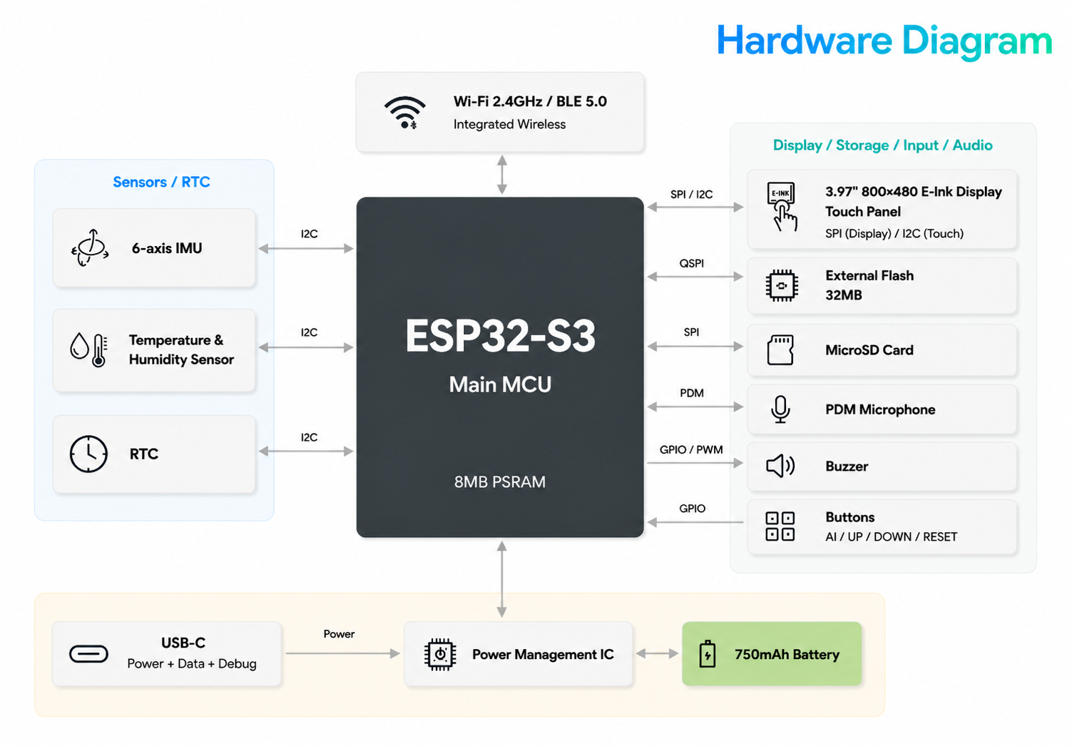
Hardware Diagram
Architecture Overview
The hardware system of reTerminal Sticky is centered on the ESP32-S3. With 8 MB of integrated PSRAM, this main controller coordinates the display, touch input, sensors, wireless connectivity, audio input, and local storage across the device.
Around the main controller, the Sticky hardware system can be understood as the following subsystems:
-
Display and touch
The 3.97-inch E-Ink display connects to the main controller through the SPI interface and is used to present text, icons, and other lightweight visual content. The touch panel connects through I2C and provides local touch input. With an 800 x 480 resolution and 4-level grayscale, the display system is well suited to low-power always-on use cases such as information boards, to-do lists, and status displays. -
Storage system
The device includes 32 MB of QSPI Flash for firmware storage and local data caching. It also supports MicroSD expansion through the SPI interface, providing additional local storage capacity when needed. -
Sensors and clock
The 6-axis IMU, temperature and humidity sensor, and RTC are connected to the main controller through I2C. Together, they support orientation detection, environmental sensing, and time keeping. These devices provide the hardware foundation for automatic screen rotation, information refresh logic, and scheduled tasks. -
Audio and local interaction
Sticky includes a built-in PDM microphone for voice input and a buzzer for basic audio prompts. The AI button, Up button, Down button, and Reset button form the main local input path on the device. -
Wireless communication system
Sticky integrates both 2.4 GHz Wi-Fi and BLE 5.0. Wi-Fi is used mainly for device networking, content synchronization, and OTA updates, while BLE is used mainly for provisioning, pairing, and short-range connection. Both are managed by the wireless subsystem inside the ESP32-S3. -
Power and debug path
The USB-C interface is used for external power input, data transfer, and device debugging. The power management circuitry coordinates USB power and battery power, while the built-in 750 mAh battery supports long-duration operation in low-power E-Ink usage scenarios.
Overall, Sticky’s hardware architecture is built around low power consumption, long-duration operation, lightweight interaction, and wireless connectivity. With the ESP32-S3 as the central controller, the device brings together display, touch, sensing, audio input, storage, and connectivity through standard interfaces such as SPI, I2C, and GPIO, enabling stable operation across typical information display and light interaction use cases.