Basic Electronics: Wired Communication Protocols in Embedded Design
In the Electronic world, communication protocols are the backbone links for an embedded system, thus they are very important for us Seeekers to understand what they are, why they are used, and the difference between communication protocols.
Also please leave us feedback. We at Seeed Studio are hoping to turn this series of blogs into wiki articles, and appreciate any feedback.
First thing first, wired communication protocols are simply a set of rules that allow two or more entities of a communication system to transmit information via physical medium. Therefore, the syntax, semantics, and synchronization of communication and possible error recovery methods between communication systems are all defined by the term “protocol”. Protocols can be implemented by both hardware and software or a combination of both. Further, each protocol has its own application area. In this blog, I will walk you though some of the most common communication protocols used in embedded designs, and of course there are plenty more for you to explore!
Types of communication protocols in embedded systems
Communication protocols are widely classified into two types, as stated in the diagram
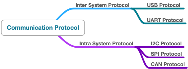
Inter system protocols are communications between two communicating devices i.e. between a PC and development boards, thus communication is via inter bus system.
USB Protocols
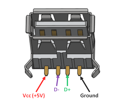
USB (Universal Serial Bus) Protocols provides a fast master/slave interface using a tiered star topology supporting up to 127 devices with up to 6 tiers. A PC is generally the master or host and each of the peripherals linked to it act as slaves or devices. USB 1.X and 2.X, use 4 lines, Vcc, Ground, and D+/D-, a twisted pair of data lines using NRZI (Non-Return to Zero Invert) encoding, as the USB pinout shown below. Data is transmitted in the form of packets, which is composed of 8 bits (1 byte) with the LSB (Least Significant Bit) transmitted first.
Advantages of USB protocol
- Fast and simple
- Plug and play functionality
- Near universal adoption
Disadvantages of USB protocol
- Requires powerful master device
- Specific drivers are required
Most of Seeed’s development boards, such as the Seeeduino 4.2 or the Wio Cat. NB1/M1 come ready with USB ports so they can easily be programmed and communicate to your PC. Some boards however must be programmed via TTL or RS232. For these we sell items such as the PL2303 USB to Serial (TTL) to help.
UART
Universal Asynchronous Receiver/Transmitter (UART) is not a communication protocol but a physical circuitry that converts parallel data into serial data. In UART communication, two UARTS communicate directly with each other. The transmitter UART converts data from a controlling device like a CPU into serial form, transits it in serial to the receiving UART, which then converts the serial data back into parallel data for the receiving device.
Only two wires are needed to transmit data between two UARTs; data flows from Tx pin of the transmitting UART to the Rx pin of the receiving UART. UART transmits data asynchronously, which means that no clock signal is needed in transmitting and receiving data. Thus, UART uses start and stop bits with actual data bits. When the receiving UART detects a start bit, it starts to read the incoming bits at a specific frequency known as the baud rate. Both UARTs must operate at about the same baud rate. The baud rate between the transmitting and receiving ends can only differ by about 10% before the timing of bits gets too far off.
Advantages of UART protocol
- Only requires two wires
- No clock signal is necessary
- Cost effective
Disadvantages of UART protocol
- The size of the data frame is limited to a maximum of 9 bits
- Doesn’t support multiple master/slave functionality
UART is very commonly used, for example, Seeeduino Cortex-M0+ provides one on-board UART, we also have our Grove – UART Wi-Fi Module, USB to UART Converter and so on.
Intra System Communication Protocols
The Intra system protocol establishes communication between components within the circuit board. In embedded systems, intra system protocol increases the number of components connected to the controllers.
On device communication protocols are known as intra system communication protocols. These are used in scenarios such as sending a sensor’s value to an MCU. Most of our Grove Modules communicate via these protocols.
Serial Peripheral Interface (SPI)
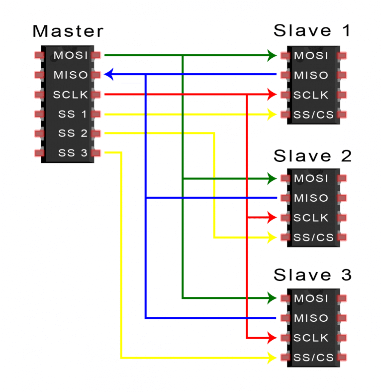
SPI (Serial Peripheral Interface) is a common communication protocol used by many different chipsets. Devices which communicate via SPI are in a master/slave relationship. The master is the controlling device (usually a micro-controller) while the slave (usually a sensor, display, or memory chip) takes instruction from the master. SPI uses 4 wires named MOSI (Master Out Slave In), MISO (Master In Slave Out, SS (Slave Select), and SCLK (Serial Clock). Further, the SS line is used to select the appropriate slave by pulling the SS low where it is normally held high. If the SS line is low the chip will begin to take instruction from the master. However a master must have multiple GPIO pins available if it is to speak with multiple slaves. To get around this, some devices will use a multiplexor to select the slaves.
SPI is full-duplex, meaning it is able to send and receive data simultaneously. While the master is providing new instructions or information via the MOSI line, the slave can return messages or results via the MISO line. This allows for faster overall throughput.
Advantages of SPI protocol
- One master supports multiple slaves
- No start and stop bits, so the data can be transmitted continuously without interruption or overhead
- Can transmit and receive simultaneously (full-duplex)
- Higher data transfer rate than I2C
Disadvantages of SPI protocol
- Require more wires than other protocols
- More slaves leads to circuit complexity
- Related to 1 and 2, this scales horribly
Inter Integrated Circuit (I2C) Communication Protocol
(I2C) Inter Integrated Circuit, pronounces “eye-two-see” or “eye-squared-see”, combines the best features of SPI and UART. With I2C, you are able to connect multiple slaves to a single master (just like SPI) or having multiple masters controlling single or even multiple slaves. This is extremely useful when you are logging data into a single LCD from more than one micro-controller. For example, our Grove – LCD RGB Backlight and our Grove – Quad Alphanumeric Display also uses I2C for communications.
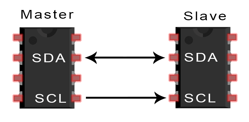
Similar to UART, I2C only uses two wires to transmit data between devices: SDA(Serial Data) and SCL(Serial Clock). Like SPI, I2C is synchronous, so the output of the bits is synchronized to the sampling of bits by a clock signal shared between the master and the slave. The clock signal is always controlled by the master.
Advantages of I2C protocol
- One master support multiple slaves connectivity
- Support multiple masters and multiple slaves
- Higher data transfer rate than I2C
- Can support over 1000 devices using just two lines
Disadvantages of I2C protocol
- Limited speed
- A single bus line for transmitting and receiving
- The size of the data frame is limited to 8 bits
CAN (Controller Area Network) Protocols
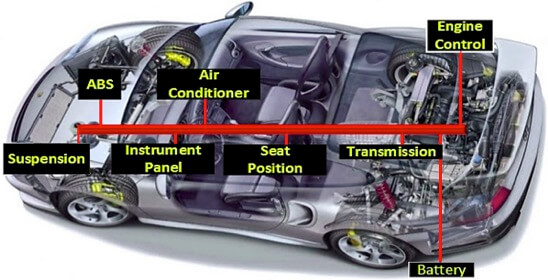
CAN protocol can be defined as the set of rules for transmitting and receiving messages in a network of electronic devices. It was designed for robust and flexible performance in harsh environments, and particularly for industrial and automotive application. In particular, CAN was developed to reduce cable wiring, so the separate electronic control units (ECUs) inside a vehicle could communicate with only pair of wires, as stated below.
Advantages of CAN protocol
- Secured and fast protocol
- Low cost and reliable
Disadvantages of CAN protocol
- Automotive oriented
- Complex protocol
And for CAN protocol, we have released several products such as the Serial Can-Bus Module, CAN-BUS Shield, of which allows you to use common industrial bus. We also just released a new RaspberryPi HAT, 2 -Chanel CAN-BUS(FD) Shield.
This blog briefly explained some of the most commonly used communication protocols used in embedded design, of which are used in different applications. I hope this provides you a little background knowledge of our products and excite you to explore more.
For more, please feel free to leave us a comment for the communication protocols you would like to like!
REFERENCE: Circuit Basics