Why Thermal Characteristics of Components are Important for Reflow Soldering

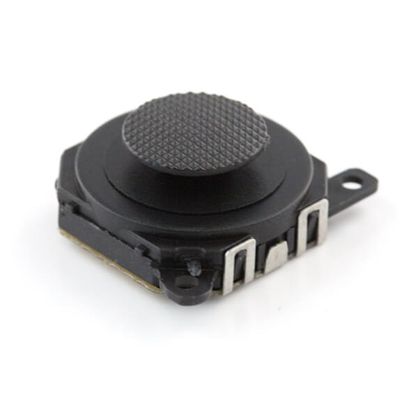
In this particular case study, the client was preparing a handheld games console to serve as a gift for guests at an upcoming conference. Making the deadline was absolutely paramount and we were not left with much room for error. It had to be a production hole-in-one. One component consisted of a joystick, provided directly by the customer but we did not have access to the datasheet. Given the strict deadline, the decision was made to do without it.
Largely made out of plastic, the joystick clearly required special treatment. However, without the datasheet, we had neither the recommended reflow profile or the maximum temperature tolerance (it was later revealed that the datasheet had none of this information anyway). Therefore, it was taken upon the engineers to do some guesswork.
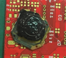
The engineers followed a general reflow profile with minor compensation for the plastic part. It was clearly not enough, as the first test samples came out of the reflow oven with the melted mess below.
The engineers then tried to solder them manually. Firstly, all the other surface mount parts were mounted onto the boards as usual. Since the pads were located on the bottom side, solder paste was applied and hot air guns were carefully used to direct heat onto the contacts. However, the plastic parts of the component body melted long before the solder paste did, resulting in more mess and wasted components.
At this stage, the customer’s design was complete, all the components had been procured and the conference date was approaching fast. There was no allowance for a re-design or part substitution.
It was then the engineers noticed that the main body was detachable from the PCB FR4 base. It was then possible to first solder the base using standard methods and then to replace the plastic body afterward. 10 pieces were first tested using this method, once verified, the rest were assembled in the same manner and the completed boards arrived a day before the conference.

As mentioned before, the component datasheet had not specified any details regarding the proper assembly of these joysticks. It is possible that the part could have been reflow soldered under the correct conditions instead of disassembling and reassembling each one. However, without precise details, we would just be wasting components.
The Reflow Profile

The purpose of the solder joint is to form a strong electrical and mechanical connection between the pad and the component contact. Typically, a good surface mount joint fully encapsulates the metallic contact and pads and forms a concave fillet. In order to achieve this for all the components on a specific board, the reflow profile should be adjusted considering the specific profiles of each component as indicated in the datasheets, with greater emphasis placed on larger or heat-sensitive parts.
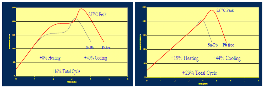
There are typically two types of reflow profiles, abbreviated RSS and RTS: the Ramp-Soak-Spike (High Soak) profile and the Ramp-to-Spike (Straight Ramp) profile respectively. RSS is the most common, having the temperature profile divided into 4-5 distinct sections.

A – Preheat
B – Soak
C – Reflow
D – Peak temperature
E – Cooling
Preheat: The rising slope of the preheating stage needs to be carefully controlled to prevent component damage and solder splatter. For example, the rapid heating of ceramic capacitors can lead to inner and outer layers expanding at an uneven rate, causing cracking. While at the same, a slow rate will extend production times. Generally, a rate between 1.5°C/s and 3°C/s is a good compromise.
Soak: During the soak phase, the solder paste is given time to expel volatile substances and for flux activation. The typical soak time is between 60 – 120 seconds. If this time is too short, it may lead to insufficient outgassing and oxide reduction, but if it is too long, the flux may become exhausted, both of which can lead to soldering defects. The RTS profile lacks this stage to reduce the amount of time the board is above the PCB’s glass transition temperature which increases the risk of board warpage.
Reflow: The reflow, or time above liquidus (TAL) stage is the section where the temperature of the oven rises above the melting temperature of the solder paste and is therefore molten. Activated flux helps the solder particles combine and helps in the formation of the intermetallic compound between the copper and solder alloy. A layer thickness of 0.5 – 1.0µm is best.
Peak temperature: The maximum temperature in the reflow profile. This temperature is determined by the most heat-sensitive component in the assembly, in this case, it would have been the joystick and would have been inferred by referencing the datasheet. Tantalum capacitors, for example, should not be heated at 260°C for more than 10 seconds.
Cooling: Similarly with preheating, steady cooling is required to prevent thermal shock and encourage the formation of a strong joint upon solidification. A steady cooling slope of about 4°C is usually recommended.
As seen in the case with the joystick, it is important to have access to the thermal properties of the components to gauge whether special assembly considerations are required. In conjunction with other factors such as solder paste type and the dimensions of the PCB boards, a suitable reflow program can be derived for optimal solder reflow.
Seeed Fusion online manufacturing services have provided Turnkey PCB Assembly services for over ten years. Pioneering the instant quoting platform, Seeed Fusion’s online system can read formatted BOM files and extract component cost and availability directly to get you a quick quote in seconds. Sourcing from partners like DigiKey and Mouser, local Chinese manufacturers and more, the Seeed Fusion PCB Assembly service is easily one of the most convenient and accessible all-in-one services out there.