What is the difference between LR and LoRaWAN?
At Seeed Studio, we have a lot of LoRa and LoRaWan products. In today’s blog, we will take you to have a deep review of LoRa and LoRaWAN.
- What is LoRa and LoraWAN?
- The differences between LoRa and LoraWAN
- LoRa Spread Spectrum Technology Introduction
- What is Spread Spectrum
- The Use of Spread Spectrum Technology
- Introduction to common terms of spread spectrum technology
- LoRaWAN frame structure
- Introduction of Hardware Solution
- Terminal equipment solution
- Gateway solution
- LoRaWAN network architecture
- LoRaWAN terminal equipment classification
- LoRaWAN terminal equipment access to the network
- OTAA(Over-The-Air Activation)
- ABP(Activation by Personalization)
- LoRaWAN terminal equipment data transmission
- Introduction of data upstream and downstream
- Basic rules of data transmission
- Introduction of ADR mechanism
- What is ADR
- What is the use of ADR
- How ADR works
- Introduction of CAD mechanism
- Air wake-up technology
- How CAD works
- CAD workflow
- CAD cycle calculation
- Preamble time calculation
- Introduction to MAC commands
1.1 The differences between LoRa and LoraWAN
LoRa is one of the low-power wide-area network communication technologies, and it is Semtech’s proprietary ultra-long-distance wireless transmission technology based on spread spectrum technology. LoRaWAN is a set of communication protocols and system architecture designed for LR long-distance communication networks. It is a media access control (MAC) layer protocol.
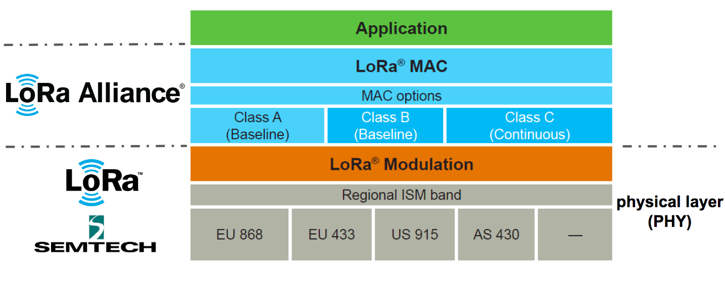
LoRa = PHY Layer
LoRaWAN = MAC Layer
1.2 LR Spread Spectrum Technology Introduction
1.2.1 What is Spread Spectrum
The baseband signal is extended to a wider frequency band by injecting a higher frequency signal. Its basic feature is that the bandwidth of the signal used to transmit information is much greater than the bandwidth of the information itself.
1.2.2 The Use of Spread Spectrum Technology
According to Shannon’s formula: C = B × log2 (1 + S / N). In this formula, C is the channel capacity in bits per second (bps), which is the maximum data rate allowed under the theoretically acceptable bit error rate (BER); B is the required channel bandwidth in Hz; S / N is the signal-to-noise power ratio. C represents the amount of information allowed by the communication channel, and also represents the desired performance. As can be seen from the above formula, by increasing the signal bandwidth (B), the communication performance (C) can be maintained or improved, and even the signal power can be lower than the noise floor (represented as strong anti-interference, farther transmission).
1.2.3 Introduction to common terms of spread spectrum technology
Bandwidth
The difference between the upper frequency and lower frequency of each channel. Increasing BW can increase the effective data rate to shorten the transmission time but at the expense of partial acceptance sensitivity. Why does increasing bandwidth sacrifice signal sensitivity?
SNR
The signal-noise ratio, the unit of measurement is dB, and its calculation method is 10lg (PS / PN). According to the calculation formula, when the SNR is less than 0, the signal power is less than the noise power, and when the SNR is greater than 0, the signal power is greater than the noise power.
RSSI
RSSI is short for receiving sensitivity (in dBm). In a pure environment, the RSSI value and the distance is a non-linear curve, so the RSSI value within a certain distance during the driving test has reference value, and there is basically no reference value after the distance.
SF
Spread spectrum modulation technology uses multiple information chips to represent each bit of the payload information. The transmission rate of the spread spectrum information is called the symbol rate (Rs), and the ratio between the chip rate and the nominal symbol rate is the spreading factor, which represents the number of symbols sent per information bit. Rs = BW / 2 ^ SF.
CR
The coding rate is the proportion of useful parts in the data stream. If the coding rate is k / n, for every k bits of useful information, the encoder generates n bits of data in total, where n-k is redundant. LR uses cyclic error correction coding for forward error detection and correction.
EIRP(Effective Isotropic Radiated Power)
Effective omnidirectional radiation power. On LR , the maximum EIRP value specified in each region is different, EIRP = P (LR chip transmit power) + G (antenna gain) – Loss (loss).
1.3 LoRaWAN frame structure
LoRa has two packet formats, explicit mode and invisible mode. There is a Header part in dominant mode, but not in invisible mode.
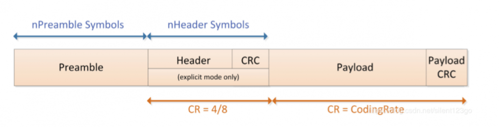
Preamble: used to keep the receiver synchronized with the incoming data stream. The default is 12 symbol lengths, and 8 symbol lengths are used in LoRaWAN. The preamble length is a variable that can be set by programming, so the length of the preamble can be extended. The length of the preamble of the receiver should be the same as that of the transmitter. If the preamble length is unknown or may change, the receiver’s preamble length should be set to the maximum value. Address filtering can be performed by setting the preamble value to achieve packet communication.
Header: contains information such as the number of bytes in the payload, the encoding rate, and whether to enable the payload CRC. The dominant mode is used in LoRaWAN. In stealth mode, these three contents need to be manually configured at both ends of the communication.
Payload: The data actually sent.
Payload CRC: CRC check of Payload, 2 bytes.
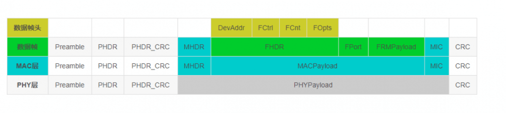
Note: When receiving a confirmed type message, the receiver should reply with a message with the confirmation bit set (ACK set to 1). If the sender is a terminal, the network sends a confirmation message to the receiving window opened by the terminal. If the sender is a gateway, the sending of the confirmation message is determined by the terminal itself.
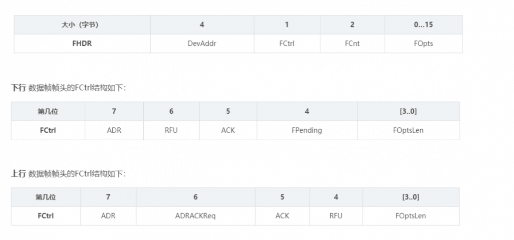
Note: Frame suspending position (FPending): only used in downlink interaction, indicating that the gateway still has data pending for delivery. At this time, the terminal is required to send an upstream message as soon as possible to open the receiving window to receive data.
FPort: 0 means there is only MAC command in FRMPayload. The FPort in the range of 1 … 223 (0x01 … 0xDF) is specified by the application; FPort = 224 is specifically for the LoRaWAN Mac layer test protocol service.
1.4 Introduction of Hardware Solution
1.4.1 Terminal equipment solution
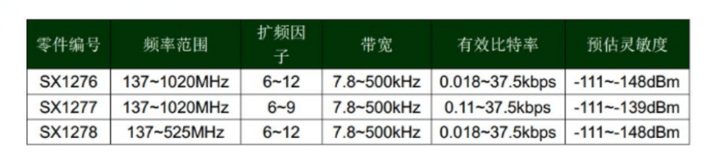
As it can be seen from the figure, the sx1276 function and frequency band coverage are the most complete. It can target European standards, American standards, Chinese standards, and international standard markets. Currently, sx1278 is generally used in China.
SX1276 / 77/78 is equipped with three different RF power amplifiers. Two of them are connected to the RFO_LF and RFO_HF pins respectively, which can realize the power amplification function up to + 14dBm. The third power amplifier is connected to the PA_BOOST pin to achieve a power amplification of up to + 20dBm through a special matching network.
RFO_LF is mainly aimed at the LF frequency band (low frequency bands 169M and 433M, 470M), RFO_HF is mainly aimed at the high frequency band (868M-915M), and PA_BOOST can cover all frequency bands. Generally, the PA_BOOST pin is now designed to ensure + 20dBM transmission power.
SPI communication can reach 10M. Generally, LoraWAN requires 10M to ensure that the SPI communication time can be ignored.
1.4.2 Gateway solution
The gateway adopts the scheme of SX1301 + SX1255 / 57
SX125X is a radio frequency front-end chip, which is responsible for the conversion between I / Q (In-phase / Quadrature, in-phase quadrature digital signal) and radio analog signals. The frequency band supported by 1255 is 400 ~ 510M, and 1257 is 862 ~ 1020M.
SX1301 is composed of 2 MCUs and ASIC (Application Specific Integrated Circuit). The main components include:
Radio frequency MCU: The MCU is connected to two SX125x through the SPI bus, which is mainly responsible for real-time automatic gain control, radio frequency calibration, and transceiver switching.
Data MCU: The MCU is responsible for allocating 8 LR modems to multiple channels. Its mechanism for arbitrating data packets includes rate, channel, radio frequency, and signal strength.
IF0 ~ IF7 channels: their bandwidth is fixed at 125kHz, and the center frequency can be set for each channel, and each channel can receive LR signals with 6 rates of SF7 ~ SF12. In theory, it can process the uplink data of 6 * 8 = 48 terminals at the same time, but it only has 8 LR demodulator, so one channel (IF0 ~ IF7) receives 6 orthogonal data packets, and the demodulator is only responsible for processing One of the.
IF8 channel: bandwidth supports 125/250 / 500kHz, used for high-speed communication between base stations.
IF9 channel: Transmit and receive (G) FSK signal, LoRaWAN uses this channel in Europe.
1.LoRaWAN network architecture
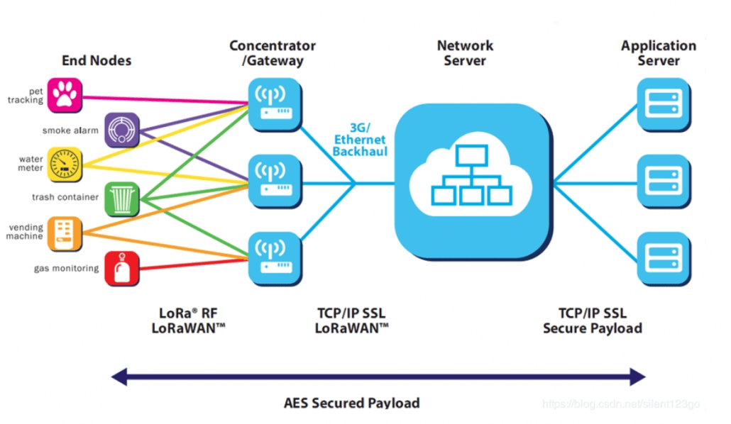
The LoRaWAN network entity is divided into four parts: end nodes, gateways, LoRaWAN servers, and user servers.
End Node: End nodes are generally all kinds of sensors, which perform data collection and switch control.
Gateway: LR gateway, which encapsulates and forwards the collected node data.
NetworkServer: Mainly responsible for the integrity check of upstream and downstream data packets.
ApplicationServer: Mainly responsible for network activation of OTAA devices and encryption and decryption of application data.
CustomerServer: Receive data from the node from the AS, perform business logic processing, and send data to the node through the API interface provided by the AS.
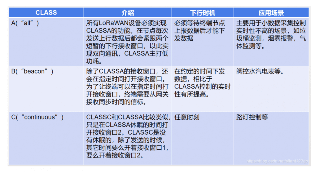
2. LoRaWAN terminal equipment classification
According to the agreement, there are Class A / B / C terminal devices, which basically cover all application scenarios of the Internet of Things. The application and differences of CLASSA / B / C can be seen in the table below
3. LoRaWAN terminal equipment access to the network
3.1 OTAA(Over-The-Air Activation)
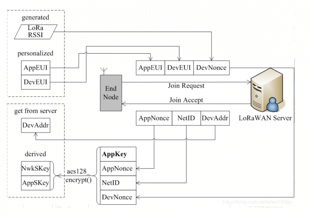
- DevEUI (device unique identifier, pre-stored by Server and Node)
- AppEUI (application unique identifier, pre-stored by Server and Node)
- AppKey (Server and Node must be stored in advance, used to encrypt and decrypt join_accept message and node is used to generate AppSKey and NwkSKey)
- DevNonce (can be obtained from the RSSI random value of the LR chip)
- The 7 least significant bits of NetID are called NwkID, which is the 7 most significant bits of DevAddr (terminal short address). NwkIDs of networks with adjacent or overlapping areas cannot be the same. The remaining 17 most significant bits are freely allocated by the network operator.
Incoming packet format
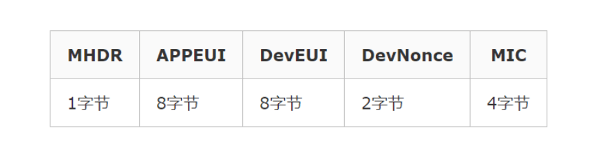
Incoming packet format
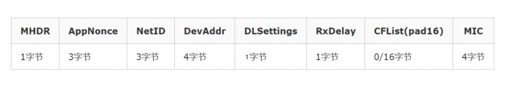
- DevAddr: Device short address, similar to IP address.
- DLSettings: The lower 4 bits indicate the rate of RX2, and the higher 4 bits indicate the rate offset of RX1.
- RxDelay: Set the time from sending completion to opening the RX1 window.
- CFList: The server brings the channel list to the terminal. Each channel occupies three bytes, and at most send 5 channels
3.2 ABP(Activation by Personalization)
This method is relatively simple. Directly configure DevAddr, NwkSKey, and AppSKey. These three parameters of the final communication of LoRaWAN no longer require the join process. In this case, the device can directly send application data.
4. LoRaWAN terminal equipment data transmission
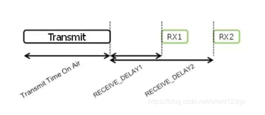
4.1 Introduction of data upstream and downstream
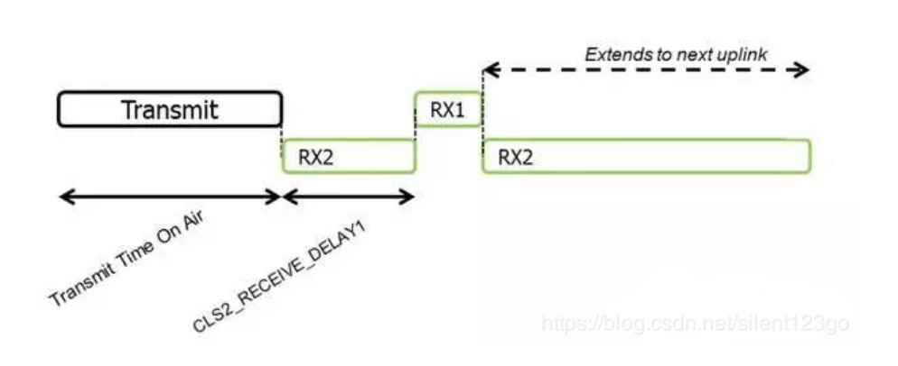
This is the timing diagram of Class A uplink and downlink. At present, the receiving window RX1 generally starts 1 second after the uplink, and the receiving window RX2 starts 2 seconds after the uplink.
Class C and A are basically the same, except that during the sleep of Class A, it has opened the receiving window RX2
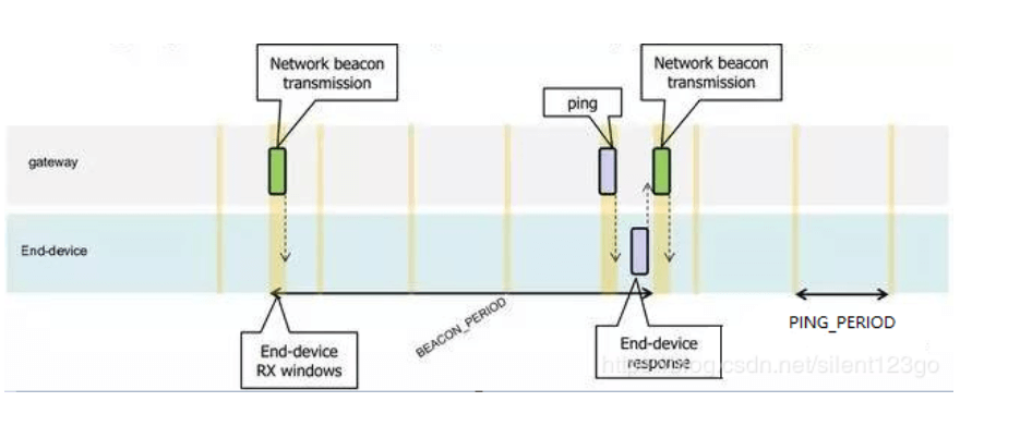
Class B time slot is more complicated, it has a synchronization time slot beacon, and a fixed period of receiving window ping time slot. As in this example, the beacon period is 128 seconds and the ping period is 32 seconds
- After the screen is added, the application data is encrypted.
- LoRaWAN stipulates that there are two types of data frames: Confirmed or Unconfirmed, that is, response type and response type. The manufacturer can choose the appropriate type according to the application needs.
- In addition, as you can see from the introduction, a major consideration at the beginning of LoRaWAN design is to support application diversity. In addition to using AppEUI to divide applications, you can also use the FPort application port to process data separately during transmission. The value range of FPort is (1 ~ 223), which is specified by the application layer.
4.2 Basic rules of data transmission
Channel switching The terminal node switches the channel randomly every time it sends a data packet. Channel switching can effectively reduce co-channel interference and wireless signal attenuation.
Duty Cycle (DutyCycle) In different countries and regions, in the ISM band, the maximum transmit duty allowed by each wireless device is limited. This is to ensure fairness and prevent illegal occupation of channels. Taking Europe as an example, DutyCycle = 1%, if a device’s transmission time is 1s, then it will not be able to transmit wireless signals (but can be received) for the next 99s.
DwellTime: This limit is mainly in North America. In the ISM band, a radio device must switch channels every 0.4s. This is done to ensure channel utilization and enhance anti-interference capabilities. For example, if the transmission time of a device is 1s, it must be tuned 3 times to complete the launch task.
5. Introduction of ADR mechanism
5.1 What is ADR
The LR network allows terminal devices to use all available data rates one by one. The LoRaWAN protocol adjusts and optimizes the data rate of the static terminal according to this feature, which is called data rate adaptation (ADR).
5.2 What is the use of ADR
When ADR is available, the network will optimize the rate so that the data rate it uses is as fast as possible. This can extend the battery life of the terminal and make full use of the network bandwidth.
5.3 How ADR works
If the data rate of the terminal is higher than the minimum rate after network optimization, then the node should periodically check to ensure that the server can still receive the uploaded data.
Every time the terminal’s upstream frame counter increments (the counter does not increment during retransmission), the device’s ADR_ACK_CNT counter also increments. If ADR_ACK_LIMIT (ADR_ACK_CNT> = ADR_ACK_LIMIT) does not receive a downlink response after the second uplink, the ADR request response bit will be set (set ADRACKReq to 1). At this time, the network is required to respond within the next ADR_ACK_DELAY uplinks. After receiving the downlink data after any uplink, the node will reset the counter ADR_ACK_CNT. During this period, the downlink data does not need to set the ACK bit, because the terminal receives any response while waiting for reception, which means that the gateway can also receive uplink data from the device. If no response is received within the next ADR_ACK_DELAY times (for example: the total number of transmissions ADR_ACK_LIMIT + ADR_ACK_DELAY), switch to a lower data rate to obtain a longer RF transmission distance and repeat the above process. Each time the terminal device reaches ADR_ACK_DELAY, it will again reduce its data rate. If the device is using the default data rate, ADRACKReq is no longer set. In this case, the transmission distance is already maximum, and no operation will be improved.
6. Introduction of CAD mechanism
6.1 Air wake-up technology
In the design of wireless sensor networks, most of the wireless transceiver nodes often require low-power processing. In order to reduce power consumption, only by reducing useless working time. In most IoT applications, the radio frequency part is in the receiving state most of the time during wireless communication, which is also the main energy consumption. When the amount of data is small in the entire wireless network, the node must be ready to receive data at any time. The ideal state is that when there is data to receive, the node is in the receiving state, and when there is no information to receive, the node is in the sleep state, which requires air wake-up technology.
From the perspective of phenomenon, it seems that the transmitter wakes up the receiver from sleep, but it is not. In fact, the receiver wakes up periodically to check whether there is a call signal in the air, if not, continue to sleep; if there is, Was awakened to receive state. Therefore, when there is no call signal in the air, the average power consumption of the receiver is lower.
But how to find the call signal, the traditional method is to judge by setting the RSSI threshold, only when the signal strength is sufficient, it is considered effective, and wake up the node, otherwise the opposite. With the application of spread spectrum modulation technology, people face many challenges when determining whether a signal that may be below the noise floor of the receiver already uses a channel. In this case, using RSSI will undoubtedly not work. To solve this problem, a channel activity detector can be used to detect the signal.
6.2 How does CAD work
6.2.1 CAD workflow
Set the frequency and spreading factor of the slave and turn on the CAD mode. When a matching (same frequency and spreading factor) signal arrives, a CADDetect interrupt will be generated, and CADDone will also be generated (whether or not a signal arrives, it will be generated CADDone interrupted). If the CADDetect interrupt is detected, it indicates that there is a signal to be received, and the slave switches to the receiving mode to receive data, otherwise, the interrupt flag is cleared and waits for the next detection.
6.2.2 CAD cycle calculation
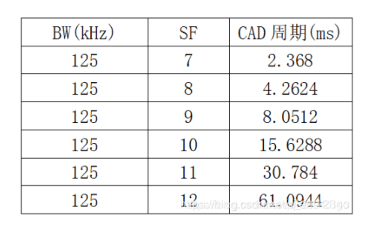
The preamble time of the sender must be longer than the entire CAD cycle, so as to ensure that the receiver normally receives data. CAD receiving time: Trec = (2 ^ SF + 32) / BW, the entire CAD cycle: Tcad = 1.85 * Trec.
6.2.3 Preamble time calculation
Tpreamble = (Npreamble + 4.25) * Tsym
Tsym = 1 / Rs
Rs = BW / (2 ^ SF)
When BW = 125kHz, SF = 7, Tpreamble = 12.544ms
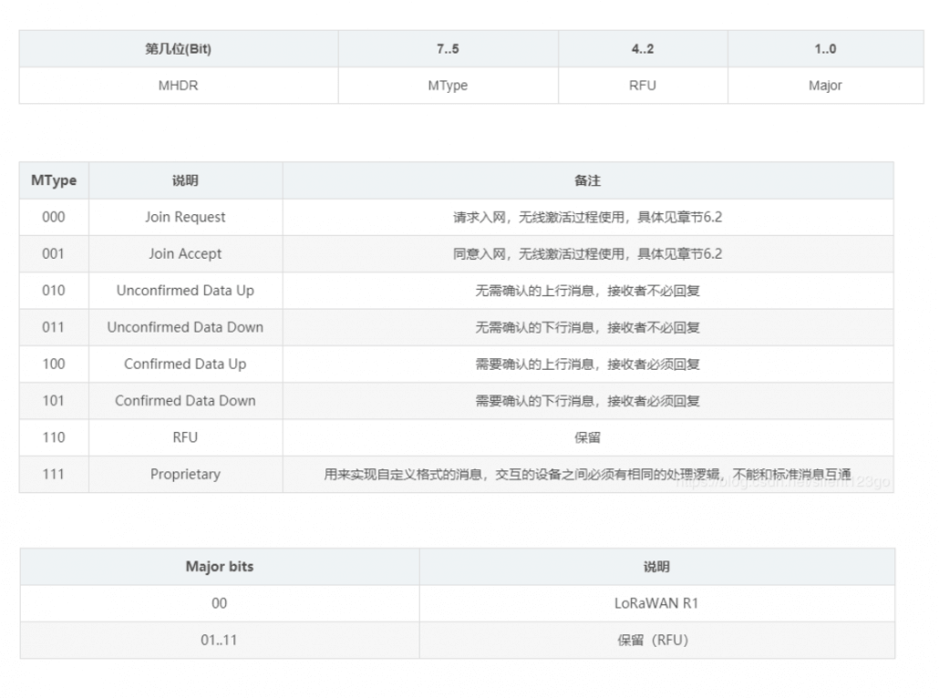
7. Introduction to MAC commands
During network management, a series of MAC commands are transmitted between the network server and the MAC layer of the terminal. MAC layer commands are never visible to applications, application servers, and applications on terminal devices.
A frame of data can contain any MAC command sequence. The MAC command can be placed in FOpts and sent together with normal data; it can also be sent separately in FRMPayload. In this case, FPort = 0, but you cannot carry MAC commands in both fields . The MAC commands placed in FOpts are not encrypted and cannot exceed 15 bytes. The MAC command placed in FRMPayload must be encrypted, and at the same time cannot exceed the maximum length of FRMPayload.
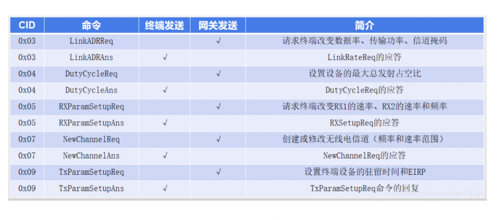
A MAC command consists of a byte of command ID (CID) and a specific command sequence, which can be empty. Common commands are shown in the table below
8. Regional parameters
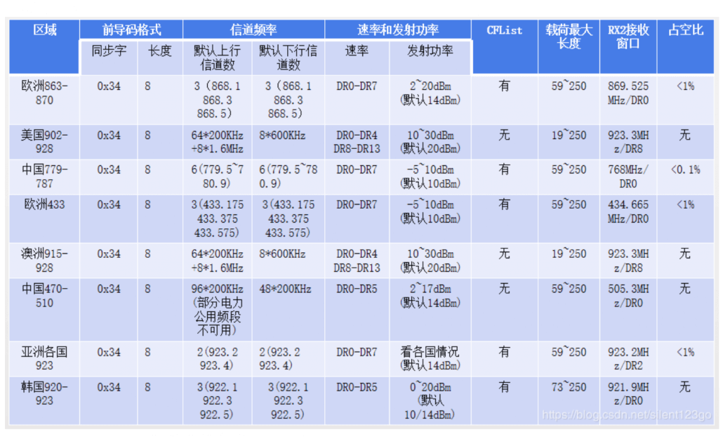
Note: There is a mapping relationship between the frequency and data rate used in the first receive window (RX1) and the frequency and data rate used in upstream transmission. The second window has a default value defined for each region, which can be modified by the MAC command.
————————————————
Copyright statement: This article is an original article of CSDN blogger “o倚楼听风雨o“, which follows the CC 4.0 BY-SA copyright agreement. Please attach the original source link and this statement to reprint.