Arduino Relay Tutorial: Control High Voltage Devices with Relay Modules
Want to control high voltage devices like your fans, lights, heaters, or other household appliances with the Arduino?
Unfortunately, you can’t as the Arduino operates at 5V which means it can’t control these higher voltage devices directly. However, with the help of a relay module to switch the high voltage, you can now use the Arduino to control those devices!
Interested? Learn how to do it through this tutorial! This Arduino relay tutorial will cover:
- What is a Relay module?
- How does the Relay works?
- Types of Relay modules here at Seeed
- Step by step instructions on how to use the relay with Arduino
Without further ado, let us jump right into the first point of this guide:
What is a Relay Module?

Before we begin, we must know what is the relay how it works before we use it to power high voltage devices.
The relay module is an electrically operated switch that can be turned on or off deciding to let current flow through or not. They are designed to be controlled with low voltages like 3.3V like the ESP32, ESP8266, etc, or 5V like your Arduino.
On top of relay modules, you will see channels which are the black cube as seen above. You may see relay modules with more channels from two channels, four channels to also eight channels.
How does the Relay works?
As mentioned above, the relay is an electrically operated switch where the relay opens when the two contacts are disconnected, while the relay is closed when the two contacts touch. When set to high, the relay will close allowing current to flow.

Even though there are many types of relays, electromechanical relays are the most commonly used which we are going to talk about them and how they work. They consist of coils, armatures, and contacts:

When the coil is energized, the induced magnetic field moves the armature, which opens or closes the contact.
Each contact connects to an input or output terminal. The input terminal is called Pole, and the output terminal is called Throw. According to the number of terminals, the relay is divided into several types. where the commonly used are the SPST and SPDT. Let’s look at how the SPST and the SPDT works:
SPST (Single Pole Single Throw)
The SPST is the simplest relay, you can consider it as a button. They have 2 terminals that can be connected or disconnected. Including 2 for the coil, an SPST relay has 4 terminals in total
This switch is normally open and when the trigger signal comes, the pole contact will connect to the throw contact which causes the switch to be closed. It is great for applications that need only an on or off state. If this the relay you are looking for, the Grove-Relay is perfect for you.

SPDT(Single Pole Double Throw):
The SPDT relay is also known as the A/B switch, as you can see below, there are two throws, this kind of relay is great for selecting between two options.

As you can see, they have three high voltage terminals that connect to the device you want to control which are the:
- COM – Common terminal
- NC – Normally closed 120 – 240V terminal
- NO – Normally open 120 – 240V terminal
And also normally additional 3 or 4 voltage pins which connect to the Arduino which are:
- 1 – Ground: Connects to the Ground on the Arduino
- 2 – 5V VCC: Connects to the 5V on the Arduino
- 3 & 4 – Signal Pins: Carries the trigger signal from the Arduino that activates the relay
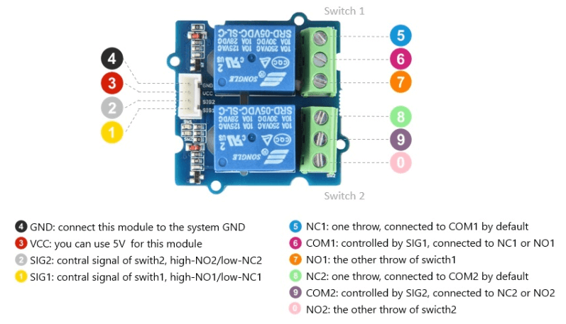
Here is an example of the pinout of an SPDT relay which is our
Grove – 2-Channel SPDT Relay:
The NC terminal is normally used if you want the relay to be closed by default which = current is flowing unless a signal is sent from the Arduino to the relay module to open the circuit and stop the current.

The NO terminal works the other way where the relay is always is open and is broken unless a signal is sent from the Arduino to close the circuit.

If you wish to light up a lamp occasionally, using a normally open circuit configuration will be better.
Types of Relay modules here at Seeed
Before we begin, we need to have a relay module! Here at Seeed, we offer various types of relays! From electromechanical relays, solid-state relays to reed relays.
For this project, we will be using electromechanical relays that are cheap, cost-effective, able to withstand large inrush currents and can carry high voltage and high current load.
Not to mention, all the electromechanical relays are Grove compatible. Grove is our modular, standardized connector prototyping system that makes connecting, experimenting and building projects easier. To find out more above Grove, you can check out our wiki page!
Here are the relay options you can consider:
Grove – Relay

- This is a simple electromechanical relay that can work low voltages like 3.3V like the ESP32, ESP8266 etc or the 5V like your Arduino with a max switching voltage 250VAC / 30VDC and current of 5A.
- There is an indicator LED on the board, which will light up when the controlled terminals get closed.
- This is an SPST relay which is great for applications that need only an on or off state.
Grove – 2-Channel SPDT Relay

- The Grove – 2-Channel SPDT Relay has two single pole – double throw (SPDT) switches. It only requires low-voltage and low current signals to control those switches. Specifically, you can use 5V DC to control max.250V AC or 110V DC.
- The best thing is that you can control the two channels separately. For instance, controlled by SIG1, you can connect the COM1 to NC1 or NO1 as you wish.
- It is so convenient and reliable that it can be applied to massive products or projects which need to switch high voltage/high current devices.
Grove – 4-Channel SPDT Relay

- The 4-channel SPDT relay is similar to the 2 channel SPDT relay but with four single pole – double throw (SPDT) switches which only require low-voltage and low current signals to control them.
- We use an onboard STM32F030F4P6 to control the channels separately. The control command is transmitted via the I2C interface, the on-board STM32F030F4P6 will parse the command so that you can control the switch you want.
Do not know which relay to pick, no worries! We compiled them into a table and compared their differences so you know which relay will suit your project needs the most!
| Relay Name | Operate voltage | Input current | Rated load | Contact resistance | Insulation resistance | Operate time | Release time | Input interface |
| Grove – Relay | 3.3V-5V | 100mA | 5A@250VAC 5A@30VDC | 50mΩ @6VDC 1A | 100MΩ | 10ms Max | 5ms Max | Digital |
| Grove – 2-Channel SPDT Relay | 5V | 90mA | 10A@250VAC 10A@30VDC | 100mΩMax. | 100MΩ Min.@500VDC | 10ms Max | 5ms Max | Digital |
| Grove – 4-Channel SPDT Relay | 5V | 90mA | 10A@250VAC 10A@30VDC | 100mΩMax. | 100MΩ Min.@500VDC | 10ms Max | 5ms Max | I2C |
Not what you are looking for? Here at Seeed, we offer over a dozen relays from electromechanical relay, solid-state relay to also reed relay. In addition, we also offer several special functions relays like a relay shield and a Heelight relay which you can control using sound commands!
Interested? Check out our Seeed Relay Selection Guide to find the relay that suits your project the most!
How to use the Relay with Arduino?
Now that we know what is the relay, how it works and which type of relay will suit your project the most, let us get started by using them with the Arduino.
For today’s example, we will be showing you how to control a relay with a button where when 1 button is pressed, the relay will close and when another button is pressed, the relay will open.
What do you need?
- Seeeduino V4.2
- Base Shield V2 – Optional, to make connections easier
- 2 x Grove – Button
- Grove – Relay
Step by step instructions
Step 1: Connect Hardware
- Firstly connect Grove-Relay to port D4 of Grove-Base Shield.
- Connect Grove-Button#1 to port D2 of Grove-Base Shield and connect Grove-Button#2 to port D3 of Grove-Base Shield.
- Plug Grove – Base Shield into Seeeduino.
- Connect Seeeduino to PC via a Micro-USB cable.
- Your connection should look something like this:

- If you do not have the base shield, you can directly connect the relay and button to the Arduino board by following the below connection:
| Grove – Relay | Arduino | Grove Cable |
| GND | GND | Black |
| VCC | 5V | Red |
| SIG | D4 | Yellow |
| Grove – Button #1 | Arduino | Grove Cable |
| GND | GND | Black |
| VCC | 5V | Red |
| SIG | D2 | Yellow |
| Grove – Button #2 | Arduino | Grove Cable |
| GND | GND | Black |
| VCC | 5V | Red |
| SIG | D3 | Yellow |
Step 2: Code
- Next, open up Arduino IDE and copy the following code into a new sketch.
// Relay Control

void setup()
{
  pinMode(2, INPUT);
  pinMode(3, INPUT);
  pinMode(4, OUTPUT);
}

void loop()
{
  if (digitalRead(2)==HIGH)
  {
    digitalWrite(4, HIGH);
    delay(100);
  }
  if (digitalRead(3)==HIGH)
  {
    digitalWrite(4, LOW);
  }
}
Step 3: Uploading Code
- After copying the code onto a new sketch, you will need to upload the demo.
- If you are unsure of how to upload the code, you can check out our guide on How to Upload Code.
And you are done! If you press the button#1 the relay should be on and if you press the button#2 the relay should be off.
As you can see, controlling the relay with the Arduino is as simple as controlling an output where you just need to send HIGH or LOW signals using an Arduino digital pin.
Want to put everything you have learned to the test? You can try to control almost any AC electronics appliances!
Warning
However, do note that when making projects that are connected to mains voltage, MAKE SURE YOU KNOW WHAT YOU ARE DOING as they involve high voltages that can cause SERIOUS INJURY OR DEATH.
Please take all necessary precautions and turn off all power to a circuit before working on it. If in doubt contact a professional such as a licensed electrician for help.
Summary
That’s all on Arduino Relay Tutorial: Control High Voltage Devices with Relay Modules! Now that you know what is the relay and how it works, possibilities are endless as you can control many high voltage devices using various devices like the TV remote, Bluetooth, internet, etc with the Arduino.
We hope you’ve found this guide useful. If you have any questions, feel free to leave them down in the comments below.