How to Prepare Assembly Drawings and Pick-and-Place Files for Seeed Fusion PCBA
📋 What This Upload Field Needs
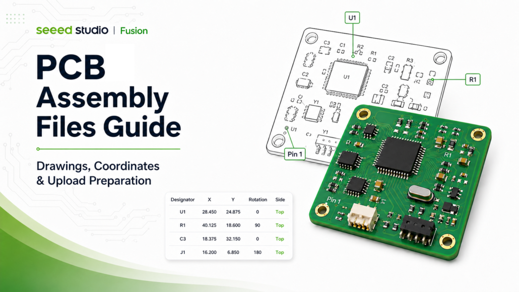
When you order PCBA on Seeed Fusion, you need a Pick-and-Place file and an Assembly Drawing. If your project has special assembly requirements, you can also include prototype photos, 3D drawings, or other reference material.
Each file answers one question:
| File | The question it answers | What it contains |
| BOM | Which components are used? | Part numbers, quantities, designators |
| Pick-and-Place file | Where does each component go? | Designator, X/Y, rotation, top/bottom |
| Assembly Drawing | How should each component be installed? | Position, outline, Pin 1, polarity, orientation |
| Reference material | Any special assembly requirements? | Prototype photos, 3D drawings, notes |
📍 What Is a Pick-and-Place File?
Centroid file, pick-and-place file, XY file, position file, and component placement list usually refer to the same thing: a data file that records the location and mounting orientation of each component. Different design tools and manufacturers may use different names.
A pick-and-place machine reads this file to get each component’s designator, X/Y coordinate, rotation, and board side, then places the SMT components accordingly. Boards with only through-hole components usually don’t need one.
A simplified example:
| Designator | X | Y | Rotation | Side |
| R1 | 25.40 mm | 18.20 mm | 90° | Top |
| U1 | 42.60 mm | 30.15 mm | 0° | Bottom |
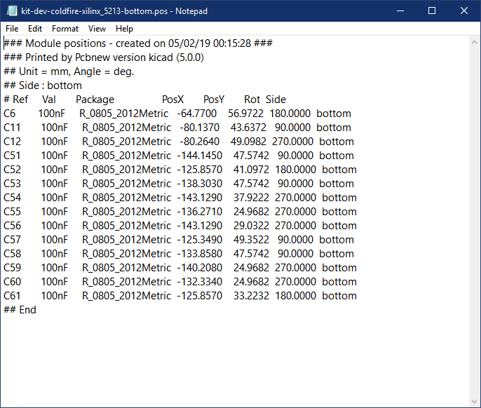
💡 Seeed Fusion accepts coordinate files in table format (CSV). Most EDA tools can export this directly, so it’s the recommended format for faster processing.
📐 What Is an Assembly Drawing?
An Assembly Drawing is the visual reference engineers use to confirm component positions and mounting orientation. A clear one shows component designators, outlines, and positions, along with direction information such as IC Pin 1, diode polarity, and connector orientation.
If both sides of the PCB carry components, provide both a Top and a Bottom Assembly Drawing. Export it as a clear, correctly oriented PDF that shows one full board side.
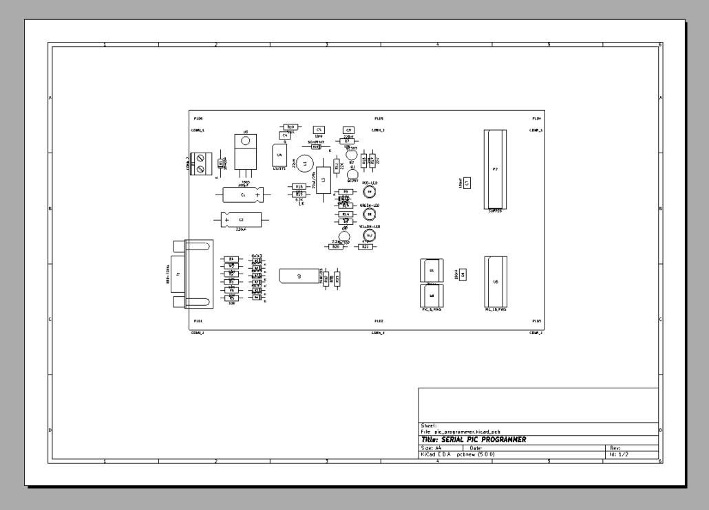
The pick-and-place file provides mounting coordinates; the Assembly Drawing provides a visual placement check. Used together, they reduce ambiguity in component position, orientation, and polarity.
🛠️ How to Export Assembly Files from Eagle
Export a Pick-and-Place File
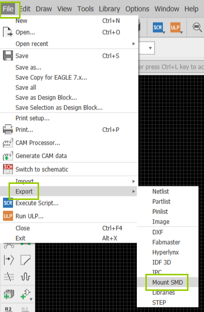
Open the .brd file in Eagle and select File > Export > Mount SMD. Eagle generates .mnt and .mnb files for the top and bottom component positions. If both sides carry SMT components, keep both files. These files can be uploaded directly; if you want table format, open them in Excel and save as CSV.
Export an Assembly Drawing
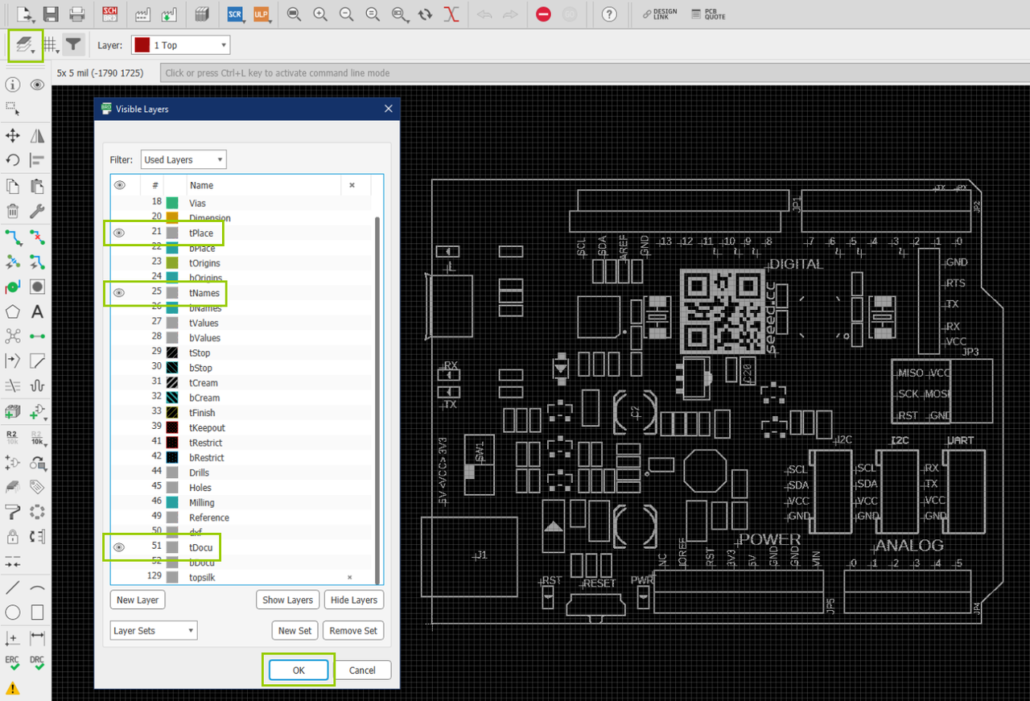
Click Layer Settings. For the top-side drawing, select these layers:
- tPlace (21)
- tNames (25)
- tDocu (51)
For the bottom side, select the matching bPlace, bNames, and bDocu layers. Then go to File > Print, adjust the preview so the full board fits clearly on one page, and print to PDF.
🛠️ How to Export Assembly Files from KiCad
Export a Pick-and-Place File
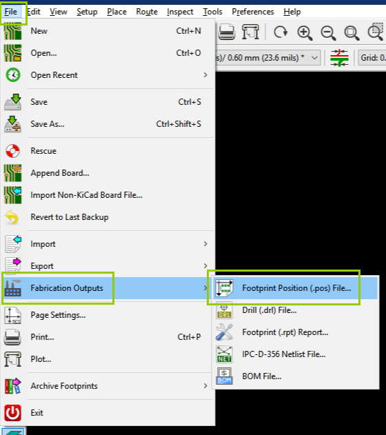
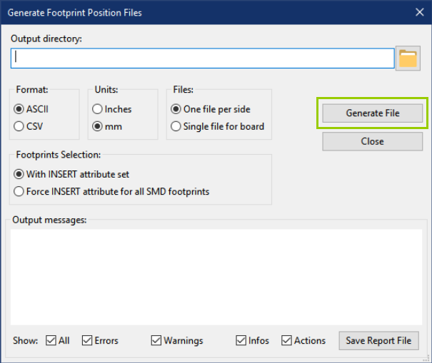
Open the .kicad_pcb file and select File > Fabrication Outputs > Footprint Position (.pos) File. Choose CSV as the export format, pick an output directory, generate the file, and confirm it includes the component data for the board sides you need.
Export an Assembly Drawing
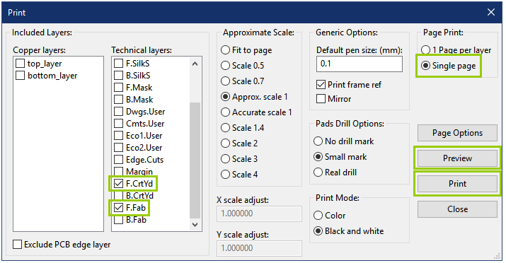
Go to File > Print. For the top-side drawing, select the F.CrtYd and F.Fab layers; for the bottom side, select B.CrtYd and B.Fab. Set the page to single-page output, check that outlines, designators, and orientation are clear in the preview, then export to PDF.
🛠️ How to Export Assembly Files from Altium Designer
Export a Pick-and-Place File
Open the .PcbDoc file and select File > Assembly Outputs > Generates Pick and Place Files. In Formats, choose CSV to export in table format. Generate the file and confirm it includes at least the component designator, X/Y coordinates, rotation, and board side.
Export an Assembly Drawing
Select File > Assembly Outputs > Assembly Drawings to open the drawing preview. Once designators, outlines, and direction markers are clear, print the drawing to PDF.
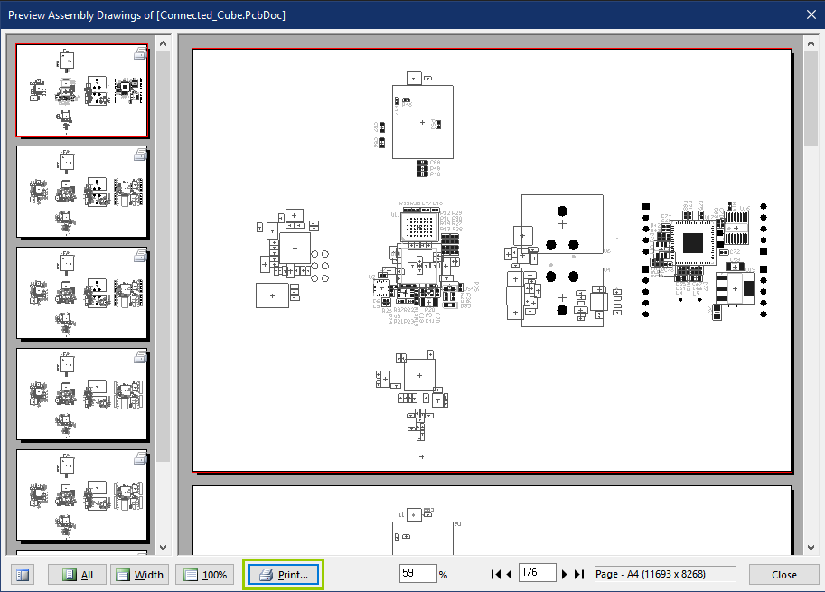
💡 Menu locations and names may differ slightly between software versions; choose the closest Fabrication Outputs or Assembly Outputs option.
📐 When to Include Additional Reference Materials
When the design files can’t fully express an assembly requirement, add reference material such as:
- Photos of a previously built PCBA or prototype;
- Photos of internal structure or connector orientation;
- A 3D view of the PCB or full product;
- Notes on special component orientation, mounting height, or mechanical fit.
Reference material helps engineers understand special requirements, but it doesn’t replace the BOM, pick-and-place file, or Assembly Drawing.
✅ Before You Upload (Read me)
This is the part worth confirming before you submit. Most file issues can be caught here — a minute of checking, grouped into two categories, saves rounds of back-and-forth later.
BOM
- From the same design revision as the pick-and-place file and Assembly Drawing, with matching designators;
- MPN, quantity, and designators for key components are complete and clear.
Assembly files (Pick-and-Place + Assembly Drawing)
- The pick-and-place file includes X/Y coordinates, rotation, and top/bottom; double-sided boards include data for both sides;
- The Assembly Drawing clearly shows designators, outlines, and orientation, with IC Pin 1, diode polarity, and connector direction identifiable;
- Special requirements are attached as photos, 3D views, or notes;
- Every file has been opened and confirmed readable before packaging, then compressed as zip / rar (under 50 MB each).
Following the prompts on the Fusion order page, upload your pick-and-place file, Assembly Drawing, and any needed reference material. Complete, clear, and revision-consistent assembly files reduce repeated confirmation and production delays.
🚀 Once your files are ready, submit your PCBA project on Seeed Fusion: https://www.seeedstudio.com/fusion_pcb.html?from=blog
About Author
