PCBA DFA Review Guide: What Engineers Check Before Assembly

Before assembly begins, engineers compare the Gerber files, BOM, and assembly files to make sure the PCB data, component list, and placement instructions agree. Even when each file looks complete on its own, a mismatch can mean that a component does not fit the pads or that its orientation cannot be confirmed.
Fusion checks for these issues during the DFA review and flags them before the order moves into assembly.
🧭 PCB DFM vs. PCBA DFA: What Each Review Covers
DFM stands for Design for Manufacturability and assesses whether a bare PCB can be fabricated within the applicable manufacturing capabilities. DFA stands for Design for Assembly and assesses whether the specified components can be assembled correctly using the submitted production files.
| PCB DFM | PCBA DFA | |
| Review subject | Bare PCB | Component assembly on the PCB |
| Core question | Can the board be fabricated? | Can the specified components be assembled correctly? |
| Typical checks | Trace width and spacing, hole size, solder mask openings, and more | File completeness, BOM-to-PCB correspondence, component package and PCB footprint matching, component interference, polarity, and orientation |
| Review stage | Before bare-board fabrication | Before PCBA assembly |
If trace width and spacing, hole size, solder mask openings, or other PCB features could affect fabrication, the issue will be raised with you before production begins. For PCBA orders, Fusion also performs a dedicated DFA review to confirm that the components, PCB data, and assembly information are consistent.
🔍 What a Fusion DFA Review Checks
📁 1. Are the Gerber Files Complete and Consistent?
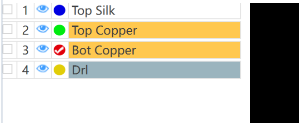
Gerber files provide the PCB data needed for a DFA review, including pad layouts and silkscreen markings. Engineers compare this data with the BOM and assembly files to confirm that each component package matches the corresponding PCB footprint and that its placement and orientation information is consistent across the files.
The Gerber files therefore need to be complete, readable, and based on the same final design version as the BOM and assembly files. Missing, unreadable, or outdated files can affect the review and delay production.
🔗 2. Does the BOM Match the PCB Data
The intended assembly scope is determined by the BOM, the assembly files, and any DNP/DNI or other assembly instructions. During the DFA review, the engineer cross-checks the reference designators, quantities, part numbers, placement positions, and assembly status of the components specified for placement.
If a discrepancy could affect component sourcing or assembly, the engineer will contact you for clarification before production.
🧩 3. Does the Component Package Match the PCB Footprint?
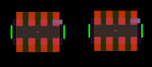
A PCB footprint is the pad layout designed for mounting and soldering a component onto the board. Using the manufacturer part number (MPN) listed in the BOM, the engineer reviews the component datasheet—including its body dimensions, pin count, pin pitch, and lead arrangement—and checks whether the component package matches the corresponding PCB footprint.
If they do not match, the component pins may not align correctly with the pads, preventing proper assembly. The DFA review identifies this type of issue before assembly begins.
📐 4. Is There Any Component Interference?
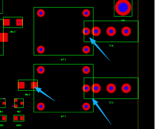
Component interference can occur when neighboring parts overlap or when there is not enough physical clearance for assembly.
The engineer uses the part numbers in the BOM to obtain the component body dimensions from their datasheets, then compares those dimensions with the component locations on the PCB to identify any physical interference or insufficient assembly clearance.
🔋 5. Are Polarity and Orientation Clear?
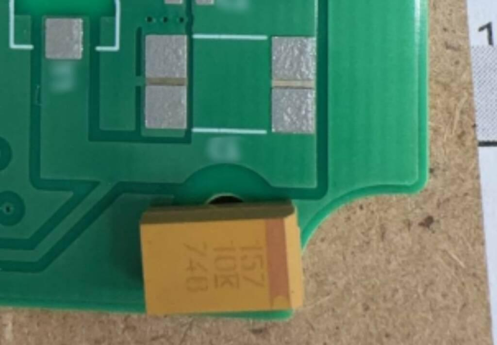
Components such as diodes, LEDs, electrolytic capacitors, and ICs have defined polarity or mounting orientations. The review checks whether the orientation indicators in the PCB footprint, silkscreen, and assembly files are clear and consistent.
If the submitted files provide conflicting orientation information, or the correct direction cannot be determined, the engineer will contact you for clarification before assembly. Clear Pin 1, polarity, and orientation markings support accurate component placement and subsequent inspection.
A DFA review focuses on assembly feasibility and consistency across the submitted production files. Circuit performance against the intended design requirements is confirmed separately through design verification and functional testing.
📄 What Happens When a DFA Issue Is Found?
If the DFA review identifies an issue that could affect assembly, Fusion will contact you before production to request additional information or confirm how the issue should be handled. In most cases, the customer updates and resubmits the relevant files; Fusion generally does not modify customer design files directly. Once the issue is resolved, the order moves into production.
🚀 Free DFA Review with Every Fusion PCBA Order
A DFA review is included as a standard engineering step with every Fusion PCBA order at no additional cost. Fusion reviews the submitted production files before assembly and identifies issues that could affect production.
When you are ready to start a PCBA project, upload your Gerber, BOM, and assembly files to configure your PCB fabrication and component assembly requirements:
About Author
