Arduino Basics and Display
This guide shows how to set up Arduino IDE and run the HelloWorld example included with the Seeed_GFX2 library on reTerminal Sticky. You can then try the Dashboard, four-level grayscale, and MicroSD image display examples.
Before You Start
Prepare the following:
- reTerminal Sticky
- A USB-C cable that supports data transfer
- A Windows, macOS, or Linux computer
- For the SD image example, a FAT32-formatted microSD card; an MBR partition scheme is recommended.
See the Hardware Overview for component locations and specifications.
Set Up the Development Environment
Step 1: Install Arduino IDE and the ESP32 Board Package
Download and install Arduino IDE from the Arduino website.
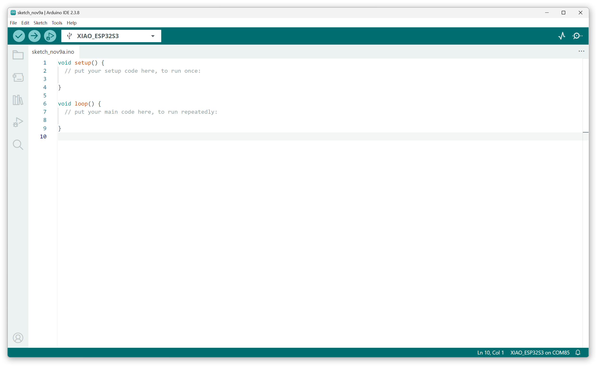
Open Preferences and add the following address to Additional Boards Manager URLs:
https://raw.githubusercontent.com/espressif/arduino-esp32/gh-pages/package_esp32_index.json
Open Boards Manager, search for esp32, and install the ESP32 board package by Espressif Systems.
Step 2: Install the Seeed_GFX2 Library
Seeed_GFX2 is Seeed Studio’s official Arduino graphics library, supporting ePaper, TFT, and OLED displays. This tutorial uses it to drive the ePaper display on Sticky.
Open the official Seeed_GFX2 repository, select the main branch, and click Code > Download ZIP to download the library.
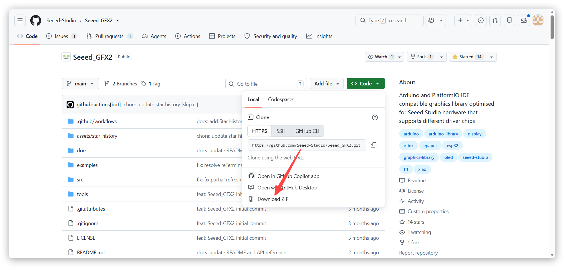
In Arduino IDE, select Sketch > Include Library > Add .ZIP Library, choose the downloaded ZIP file, and complete the installation.
Step 3: Select the Board and Port
-
Connect Sticky to your computer with the USB-C data cable.
-
Select XIAO_ESP32S3 under Tools > Board > ESP32 Arduino and leave the other options at their defaults.
-
Select the CH343P port under Tools > Port. For example, Windows Device Manager usually lists it as USB-Enhanced-SERIAL CH343 (COM number). Use the actual port number shown for your device.
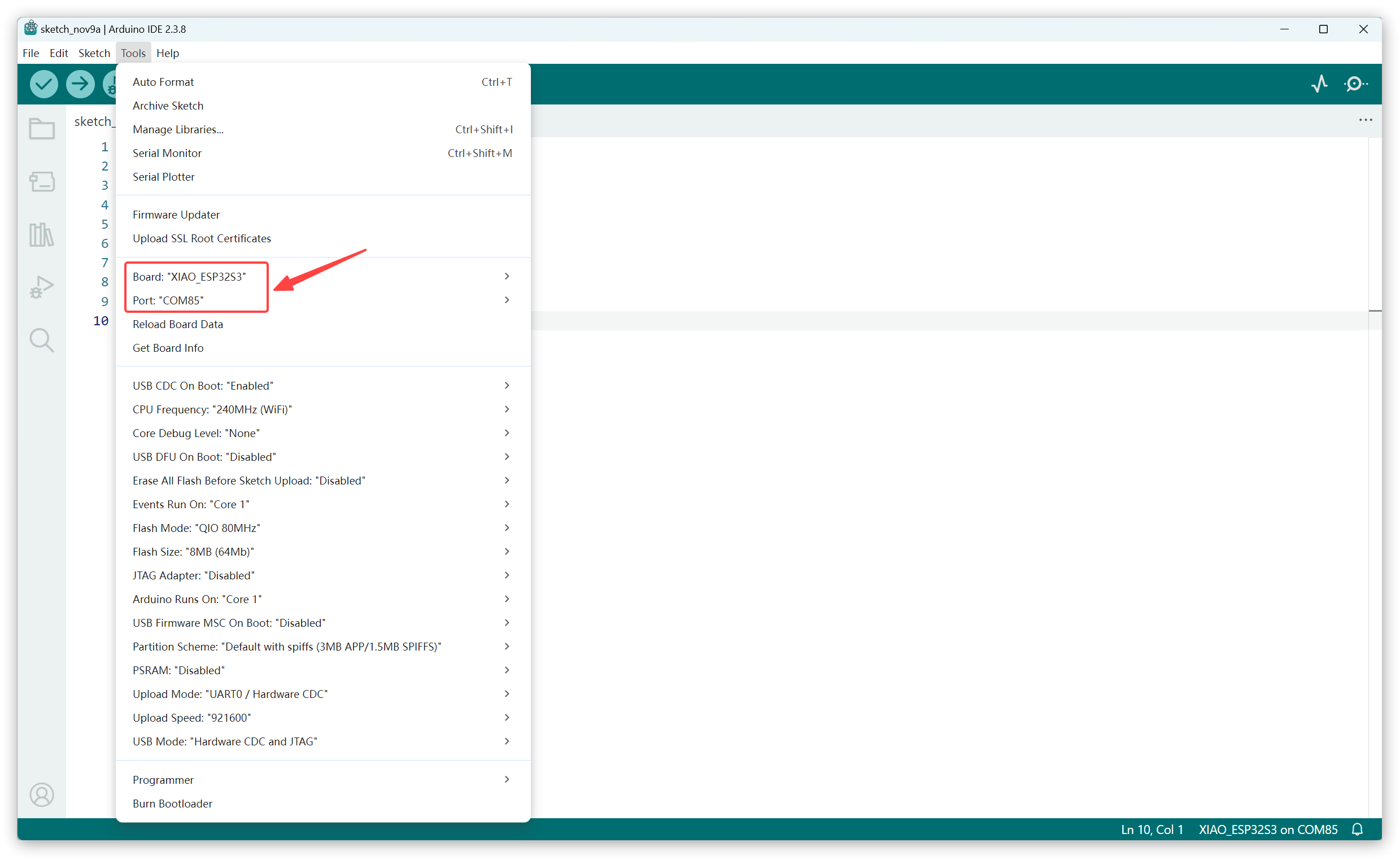
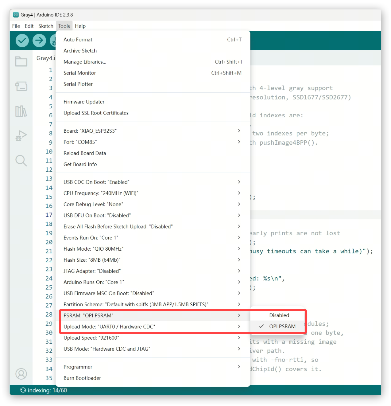
Before running the Gray4 and SD image examples, select OPI PSRAM under Tools > PSRAM. See the corresponding sections for details.
Run HelloWorld
Step 1: Open the Built-In Example
In Arduino IDE, open:
File > Examples > Seeed_GFX2 > ePaper Displays > reTerminal E Series > reTerminal Sticky > HelloWorld
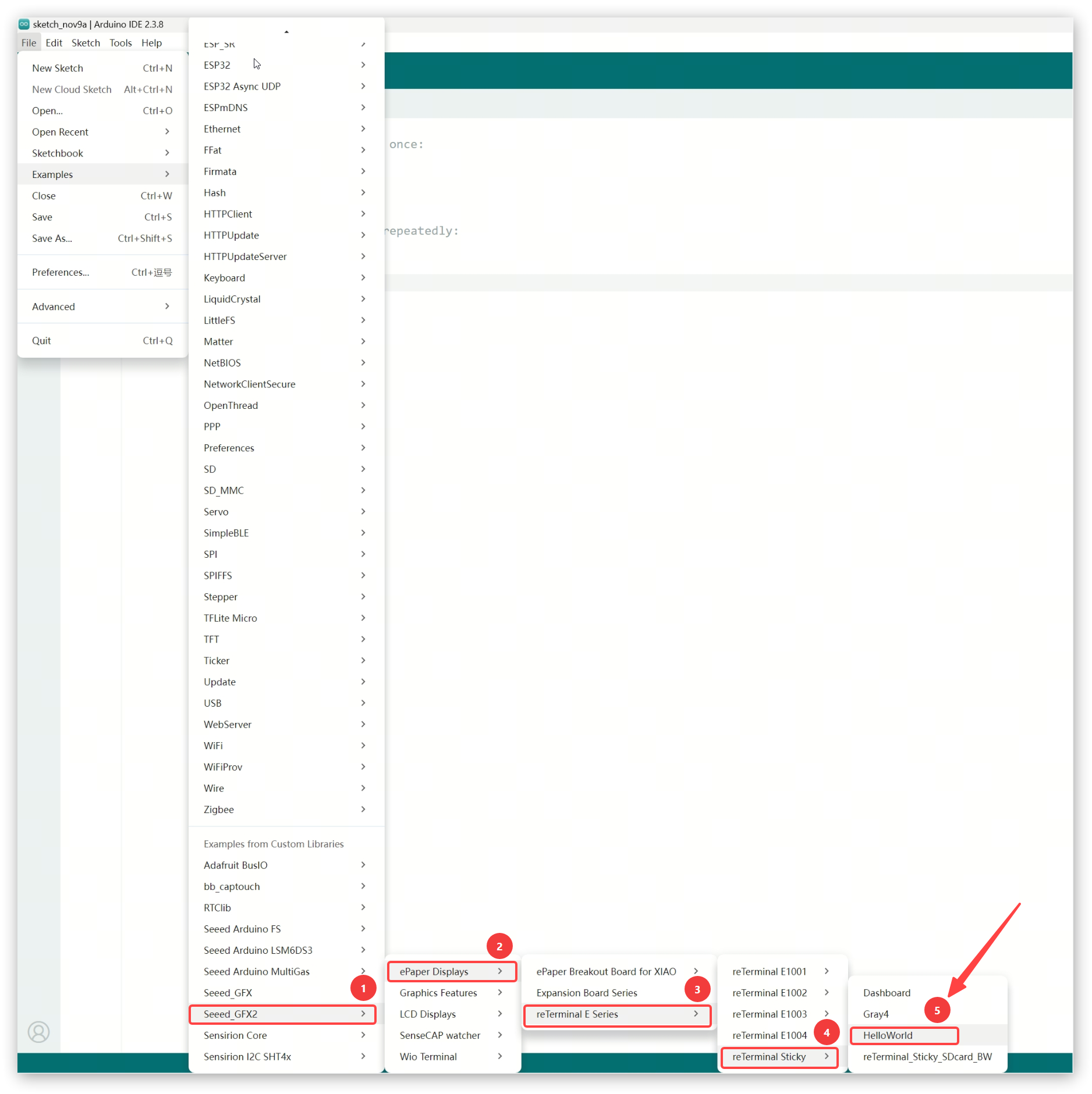
The sketch already includes the Sticky product configuration:
#include <Seeed_GFX.h>

Seeed_GFX display(Seeed_Product::reTerminal_Sticky);
Leave this configuration unchanged for the first run. Drawing functions update the buffer first, and the e-paper refreshes when update() is called.
The Sticky product configuration automatically detects the display controller, selects the SSD1677 or SSD2677 driver, and sets the display orientation. Place the device with its physical buttons at the top.
Step 2: Compile and Upload
Check that the current window still has XIAO_ESP32S3 and Sticky’s port selected. Click Verify (the checkmark icon) and wait for compilation to finish. If it fails, use the troubleshooting table at the end of this guide before continuing.
Click Upload (the right-arrow icon) and wait for the IDE to report completion. Keep USB connected throughout the upload.
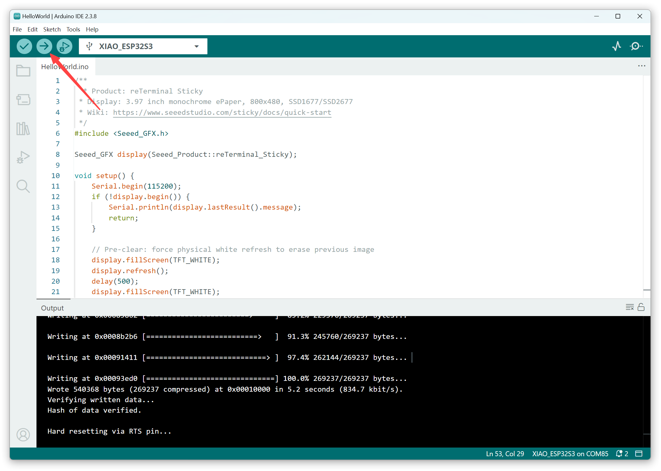
Uploading replaces Sticky’s current firmware. Save anything you need first. The Seeedash App features of the official firmware are unavailable while this example is running.
Step 3: Check the Display
Wait for the device to start and the screen refresh to finish. The display should show the reTerminal Sticky heading at the top, Hello World in the center, and Seeed Studio information at the bottom. Flashing during an e-paper refresh is normal. The example draws once and leaves the image on screen.
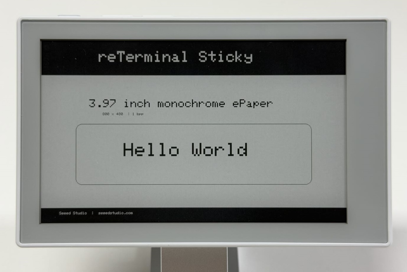
Once HelloWorld appears, try the optional examples below or continue to the onboard-peripheral guide.
Try More Display Examples
The following three examples are in the same folder as HelloWorld. In Arduino IDE, find reTerminal Sticky under File > Examples and select the example you want to run.
1. Dashboard: Text and Graphics
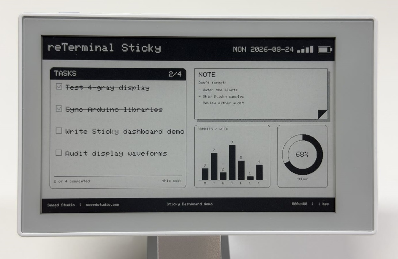
Open the Dashboard example, compile and upload the sketch, then wait for the dashboard to appear on the screen.
Code Explanation
The example uses drawString() and fillRect() to draw text and rectangles, setTextDatum() to align text, and drawArc() to draw the progress ring. It calls update() to refresh the screen. The drawing area is 800 × 480, with the origin at the upper-left corner.
Expected result
The screen shows a sample dashboard with task cards, text, icons, and progress graphics. The date, tasks, and battery icon use fixed sample data and do not represent live network information or the device’s actual battery status.
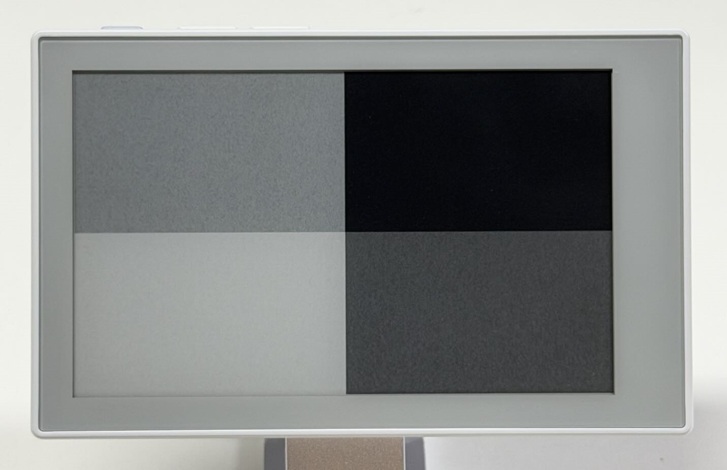
2. Gray4: Four-Level Grayscale
Step 1. Open Gray4 and keep the supplied image.h with the sketch. Do not copy only the .ino file.
Step 2. Select OPI PSRAM under Tools > PSRAM, then compile and upload.
Code Explanation
display.panel().configure(PanelMode::Gray4) switches to four-level grayscale mode. pushImage4BPP() draws the image data from image.h into the buffer, and refresh() updates the screen.
Expected result
The screen is divided into four areas, displaying black, dark gray, light gray, and white to demonstrate four-level grayscale.
3. MicroSD: Image Display
Prepare a FAT32-formatted microSD card. An MBR (Master Boot Record) partition scheme is recommended. Back up your files before formatting the card.
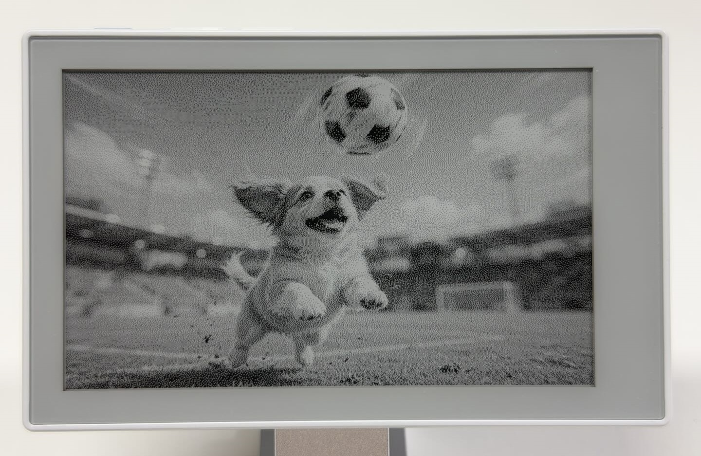
We recommend using an 800 × 480 baseline JPEG image. Images of other sizes are scaled to fill the screen and may appear stretched if their aspect ratio differs from the screen’s.
Step 1. Create a folder named img in the root directory of the microSD card. Rename your image to demo.jpg and place it inside the folder.
microSD/
└── img/
    └── demo.jpg
Step 2. Insert the card into Sticky and open reTerminal_Sticky_SDcard_BW. Keep image_loader.h/.cpp, pngle.h/.c, and miniz.h/.c in the same directory; no separate decoder library is needed. Check that the image path remains:
static const char* IMAGE_PATH = "/img/demo.jpg";
Step 3. Select OPI PSRAM under Tools > PSRAM, compile and upload, then wait for image loading and screen refresh to finish.
Expected result
The image is displayed using black-and-white dithering, with patterns of black and white pixels representing different shades. Unlike Gray4, this example uses only black and white.
FAQ
| Symptom | What to do |
|---|---|
| No device appears under Tools > Port | Try another data cable or USB port. On Windows, check whether Device Manager recognizes the CH343P USB serial device; resolve any driver error first |
| Seeed_GFX2 or the Sticky examples cannot be found | Confirm Seeed_GFX2 is installed from the ZIP and reopen the IDE. Check that the installed version includes the Sticky examples and that compiler output selects Seeed_GFX2 rather than another library with the same header name |
| Compilation succeeds but upload fails | Recheck the board and port in the current window. Close monitors or other programs using the port; lower Upload Speed if the connection is unstable |
| Upload finishes but the previous image remains | Wait for startup and the full refresh. If nothing changes, confirm you uploaded Sticky’s HelloWorld with the correct board settings and retain the IDE output for troubleshooting |
| Gray4 shows no image or reports a memory error | Check OPI PSRAM and keep image.h with the example. Run unmodified Gray4 first to rule out problems in custom image data |
| The SD picture does not appear | Check insertion, filesystem, and /img/demo.jpg. For IMAGE DECODE FAILED, try baseline JPEG at about 800 × 480. Card capacity alone does not determine compatibility |
Next Step
Continue with Arduino Onboard Peripherals to explore standalone examples for buttons, the buzzer, and onboard sensors.