Arduino Onboard Peripherals
With the Arduino environment and display basics covered in Arduino Basics and Display, this guide moves on to Sticky’s buttons, buzzer, temperature and humidity sensor, IMU, battery, and MicroSD. Each peripheral has a standalone sketch you can upload independently.
Select File > New Sketch and replace the default code with the complete code for the example you want to run. Uploading replaces the program on the device. Each section lists its libraries and reference versions.
These examples send their results through Serial1. Select the CH343P port, open Tools > Serial Monitor, and set it to 115200 baud. If you miss the startup output, leave Serial Monitor open and press the RESET button on the device to view it again.
User Buttons
This example detects presses and releases of AI / OK, UP, and DOWN and prints a message for each event. No additional library is needed.
| Button | GPIO | Pressed level |
|---|---|---|
| AI / OK | GPIO4 | LOW |
| UP | GPIO5 | LOW |
| DOWN | GPIO6 | LOW |
Create a new sketch, copy the complete code below, click Verify, then Upload after compilation finishes.
/*
 * reTerminal Sticky - Button Example
 *
 * Reads the onboard AI / OK, UP, and DOWN buttons and prints their events.
 */

#include <Arduino.h>

// CH343P UART connection: ESP32-S3 RX on GPIO44, TX on GPIO43.
constexpr int PIN_SERIAL_RX = 44;
constexpr int PIN_SERIAL_TX = 43;

// GPIO45 keeps the main power rail enabled.
constexpr int PIN_POWER_HOLD = 45;

// GPIO46 keeps the power controller locked on.
constexpr int PIN_POWER_LOCK = 46;

// AI / OK button on GPIO4, active LOW.
constexpr int PIN_BUTTON_AI = 4;

// UP button on GPIO5, active LOW.
constexpr int PIN_BUTTON_UP = 5;

// DOWN button on GPIO6, active LOW.
constexpr int PIN_BUTTON_DOWN = 6;

constexpr int BUTTON_PINS[] = {
  PIN_BUTTON_AI,
  PIN_BUTTON_UP,
  PIN_BUTTON_DOWN
};
const char* BUTTON_NAMES[] = {"AI / OK", "UP", "DOWN"};
constexpr int BUTTON_COUNT = 3;
constexpr unsigned long DEBOUNCE_MS = 30;

bool lastReading[BUTTON_COUNT];
bool stableState[BUTTON_COUNT];
unsigned long lastChange[BUTTON_COUNT];

void keepPowerOn() {
  pinMode(PIN_POWER_HOLD, OUTPUT);
  pinMode(PIN_POWER_LOCK, OUTPUT);
  digitalWrite(PIN_POWER_HOLD, HIGH);
  digitalWrite(PIN_POWER_LOCK, HIGH);
}

void setup() {
  keepPowerOn();

  Serial1.begin(115200, SERIAL_8N1, PIN_SERIAL_RX, PIN_SERIAL_TX);
  delay(200);

  Serial1.println();
  Serial1.println("reTerminal Sticky Button Example");
  Serial1.println("Press AI / OK, UP, or DOWN to test.");

  for (int i = 0; i < BUTTON_COUNT; ++i) {
    pinMode(BUTTON_PINS[i], INPUT_PULLUP);
    lastReading[i] = digitalRead(BUTTON_PINS[i]);
    stableState[i] = lastReading[i];
    lastChange[i] = millis();
  }
}

void loop() {
  for (int i = 0; i < BUTTON_COUNT; ++i) {
    const bool reading = digitalRead(BUTTON_PINS[i]);

    if (reading != lastReading[i]) {
      lastReading[i] = reading;
      lastChange[i] = millis();
    }

    // Report a change only after the input has remained stable.
    if (millis() - lastChange[i] >= DEBOUNCE_MS &&
        reading != stableState[i]) {
      stableState[i] = reading;
      Serial1.print(BUTTON_NAMES[i]);
      Serial1.println(reading == LOW ? " pressed" : " released");
    }
  }

  delay(5);
}
Code Explanation
INPUT_PULLUPenables the internal pull-up, so a released button readsHIGHand a pressed button readsLOW.- The sketch reads each button with
digitalRead()and usesmillis()to track input changes. It reports a press or release only when the input has remained stable for at least 30 ms and differs from the previously confirmed state.
Expected Output
Open Serial Monitor, briefly press each of the three buttons, then hold one for about a second and release it. Each press and release prints the button name with pressed or released. Holding a button does not continuously repeat the event.
reTerminal Sticky Button Example
Press AI / OK, UP, or DOWN to test.
AI / OK pressed
AI / OK released
UP pressed
UP released
DOWN pressed
DOWN released
Buzzer Control
The onboard buzzer is connected to GPIO48. Use Arduino’s tone() to play three short tones at different frequencies. No additional library is needed.
Copy the complete code into a new sketch, compile, and upload.
/*
 * reTerminal Sticky - Buzzer Example
 *
 * Plays three short tones at low, medium, and high frequencies.
 */

#include <Arduino.h>

// CH343P UART connection: ESP32-S3 RX on GPIO44, TX on GPIO43.
constexpr int PIN_SERIAL_RX = 44;
constexpr int PIN_SERIAL_TX = 43;

// GPIO45 keeps the main power rail enabled.
constexpr int PIN_POWER_HOLD = 45;

// GPIO46 keeps the power controller locked on.
constexpr int PIN_POWER_LOCK = 46;

// Onboard buzzer on GPIO48.
constexpr int PIN_BUZZER = 48;

void keepPowerOn() {
  pinMode(PIN_POWER_HOLD, OUTPUT);
  pinMode(PIN_POWER_LOCK, OUTPUT);
  digitalWrite(PIN_POWER_HOLD, HIGH);
  digitalWrite(PIN_POWER_LOCK, HIGH);
}

void playTone(const char* name, unsigned int frequency) {
  Serial1.print("Playing ");
  Serial1.print(name);
  Serial1.print(" tone: ");
  Serial1.print(frequency);
  Serial1.println(" Hz");

  tone(PIN_BUZZER, frequency, 200);
  delay(250);  // Let the 200 ms tone finish before the next pitch.
  noTone(PIN_BUZZER);
}

void setup() {
  keepPowerOn();

  Serial1.begin(115200, SERIAL_8N1, PIN_SERIAL_RX, PIN_SERIAL_TX);
  delay(200);

  Serial1.println();
  Serial1.println("reTerminal Sticky Buzzer Example");
  Serial1.println("Playing three test tones...");

  playTone("low", 600);
  delay(150);
  playTone("medium", 900);
  delay(150);
  playTone("high", 1200);

  Serial1.println("Buzzer test complete");
}

void loop() {
  delay(1000);
}
Code Explanation
tone(PIN_BUZZER, frequency, 200)sets the buzzer frequency and a duration of 200 ms. Changefrequencyto adjust the pitch, and usenoTone()to stop the output.playTone()prints the tone name and frequency, then plays the tone.setup()calls it in sequence for the three tones;loop()does not repeat the sequence.
Expected Output
Open Serial Monitor, listen for three short tones, and check the frequencies and completion message. The tones play at 600, 900, and 1200 Hz, each about 200 ms long. The sequence finishes with Buzzer test complete.
reTerminal Sticky Buzzer Example
Playing three test tones...
Playing low tone: 600 Hz
Playing medium tone: 900 Hz
Playing high tone: 1200 Hz
Buzzer test complete
The tones play once at startup and are not repeated in a loop.
Reading Temperature and Humidity
Sticky has an onboard SHT40 temperature and humidity sensor. This example reads both values and prints them over serial.
| Setting | Value |
|---|---|
| I2C SDA / SCL | GPIO1 / GPIO0 |
| I2C clock | 400 kHz |
| SHT40 address | 0x44 |
The SHT40, IMU, and battery gauge share these I2C pins and use separate device addresses.
Step 1. Open Library Manager and install Sensirion I2C SHT4x by Sensirion, including its Sensirion Core dependency. Reference versions are 1.1.2 and 0.7.3.
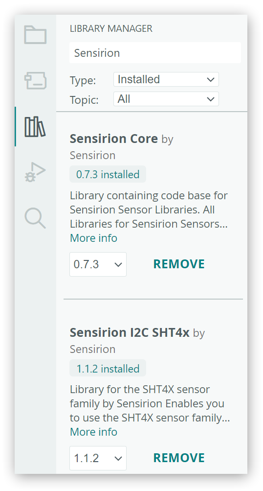
Step 2. Copy the complete code below into a new sketch, compile, and upload.
/*
 * reTerminal Sticky - SHT40 Example
 *
 * Reads temperature and relative humidity from the onboard SHT40 sensor.
 */

#include <Arduino.h>
#include <Wire.h>
#include <SensirionCore.h>
#include <SensirionI2cSht4x.h>

// CH343P UART: ESP32-S3 RX on GPIO44, TX on GPIO43.
constexpr int PIN_SERIAL_RX = 44;
constexpr int PIN_SERIAL_TX = 43;

// Main power hold and power lock signals, both active HIGH.
constexpr int PIN_POWER_HOLD = 45;
constexpr int PIN_POWER_LOCK = 46;

// Onboard sensor I2C bus: GPIO1 -> SDA, GPIO0 -> SCL.
constexpr int PIN_I2C_SDA = 1;
constexpr int PIN_I2C_SCL = 0;
constexpr uint32_t I2C_FREQUENCY = 400000;

// Onboard SHT40 I2C address.
constexpr uint8_t SHT40_ADDRESS = 0x44;

SensirionI2cSht4x sht40;

void keepPowerOn() {
  pinMode(PIN_POWER_HOLD, OUTPUT);
  pinMode(PIN_POWER_LOCK, OUTPUT);
  digitalWrite(PIN_POWER_HOLD, HIGH);
  digitalWrite(PIN_POWER_LOCK, HIGH);
}

void setup() {
  keepPowerOn();

  Serial1.begin(115200, SERIAL_8N1, PIN_SERIAL_RX, PIN_SERIAL_TX);
  delay(200);
  Serial1.println();
  Serial1.println("reTerminal Sticky SHT40 Example");

  Wire.begin(PIN_I2C_SDA, PIN_I2C_SCL, I2C_FREQUENCY);
  sht40.begin(Wire, SHT40_ADDRESS);

  Serial1.println("Reading temperature and humidity every 5 seconds...");
}

void loop() {
  float temperature = 0.0f;
  float humidity = 0.0f;
  const uint16_t error = sht40.measureHighPrecision(temperature, humidity);

  // The library returns a status code separately from the measured values.
  if (error != 0) {
    char errorMessage[64];
    errorToString(error, errorMessage, sizeof(errorMessage));
    Serial1.print("SHT40 read failed: ");
    Serial1.println(errorMessage);
  } else {
    Serial1.print("Temperature: ");
    Serial1.print(temperature, 2);
    Serial1.print(" C, Humidity: ");
    Serial1.print(humidity, 2);
    Serial1.println(" %RH");
  }

  delay(5000);
}
Code Explanation
Wire.begin()configures the I2C pins and clock.sht40.begin(Wire, SHT40_ADDRESS)selects the bus and address for the SHT40.measureHighPrecision(temperature, humidity)fills the two variables with temperature and relative humidity and returns a status code. The sketch prints readings when the status is0; otherwise,errorToString()converts the error code into a readable message.
Expected Output
Open Serial Monitor and observe at least two readings. Temperature and relative humidity are printed about every five seconds in the following format. Readings vary with the surroundings.
reTerminal Sticky SHT40 Example
Reading temperature and humidity every 5 seconds...
Temperature: 27.43 C, Humidity: 59.38 %RH
Temperature: 27.44 C, Humidity: 59.35 %RH
If the sketch reports SHT40 read failed at runtime, check that the I2C pins and address match the table and read the error message in Serial Monitor.
Reading IMU Data
The onboard LSM6DS3TR-C measures three-axis acceleration and angular velocity. This example reads both and shows how they change as you move the device.
| Setting | Value |
|---|---|
| I2C SDA / SCL | GPIO1 / GPIO0 |
| I2C clock | 400 kHz |
| LSM6DS3TR-C address | 0x6A |
Step 1. Install Seeed Arduino LSM6DS3 by Seeed Studio in Library Manager (reference version 2.0.7).
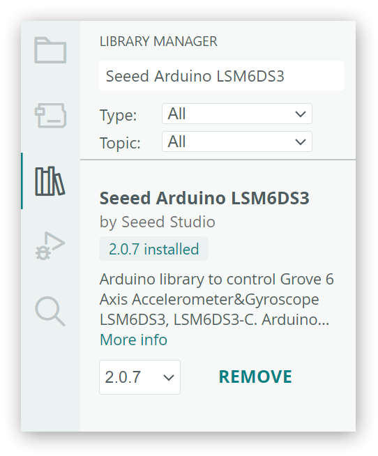
Step 2. Copy the complete code below into a new sketch, compile, and upload.
/*
 * reTerminal Sticky - IMU Example
 *
 * Reads acceleration and angular velocity from the onboard LSM6DS3TR-C IMU.
 */

#include <Arduino.h>
#include <Wire.h>
#include <LSM6DS3.h>

// CH343P UART: ESP32-S3 RX on GPIO44, TX on GPIO43.
constexpr int PIN_SERIAL_RX = 44;
constexpr int PIN_SERIAL_TX = 43;

// Main power hold and power lock signals, both active HIGH.
constexpr int PIN_POWER_HOLD = 45;
constexpr int PIN_POWER_LOCK = 46;

// Onboard sensor I2C bus: GPIO1 -> SDA, GPIO0 -> SCL.
constexpr int PIN_I2C_SDA = 1;
constexpr int PIN_I2C_SCL = 0;
constexpr uint32_t I2C_FREQUENCY = 400000;

// Onboard LSM6DS3TR-C I2C address.
constexpr uint8_t IMU_ADDRESS = 0x6A;

LSM6DS3 imu(I2C_MODE, IMU_ADDRESS);

void keepPowerOn() {
  pinMode(PIN_POWER_HOLD, OUTPUT);
  pinMode(PIN_POWER_LOCK, OUTPUT);
  digitalWrite(PIN_POWER_HOLD, HIGH);
  digitalWrite(PIN_POWER_LOCK, HIGH);
}

void setup() {
  keepPowerOn();

  Serial1.begin(115200, SERIAL_8N1, PIN_SERIAL_RX, PIN_SERIAL_TX);
  delay(200);
  Serial1.println();
  Serial1.println("reTerminal Sticky IMU Example");

  Wire.begin(PIN_I2C_SDA, PIN_I2C_SCL, I2C_FREQUENCY);

  if (imu.begin() != 0) {  // Seeed's begin() returns 0 on success.
    Serial1.println("LSM6DS3TR-C initialization failed");
    Serial1.println("Check the I2C connection and reset the device.");
    while (true) {
      delay(1000);
    }
  }

  Serial1.println("Move or rotate the device to change the readings.");
}

void loop() {
  Serial1.print("Accel (g) X: ");
  Serial1.print(imu.readFloatAccelX(), 3);
  Serial1.print("  Y: ");
  Serial1.print(imu.readFloatAccelY(), 3);
  Serial1.print("  Z: ");
  Serial1.println(imu.readFloatAccelZ(), 3);

  Serial1.print("Gyro (dps) X: ");
  Serial1.print(imu.readFloatGyroX(), 2);
  Serial1.print("  Y: ");
  Serial1.print(imu.readFloatGyroY(), 2);
  Serial1.print("  Z: ");
  Serial1.println(imu.readFloatGyroZ(), 2);
  Serial1.println();

  delay(1000);
}
Code Explanation
LSM6DS3 imu(I2C_MODE, IMU_ADDRESS)selects the I2C interface and device address. After initializing the bus, the sketch callsimu.begin()to initialize the sensor. This Seeed library returns0on success; the sketch stops taking readings if initialization fails.readFloatAccelX()andreadFloatGyroX()read X-axis acceleration and angular velocity. The corresponding functions read the Y and Z axes.
Expected Output
Open Serial Monitor. Place the device flat and observe a reading, then slowly tilt and rotate it to compare the axes. A set of acceleration and angular velocity readings is printed about once a second.
reTerminal Sticky IMU Example
Move or rotate the device to change the readings.
Accel (g) X: -0.023  Y: 0.005  Z: 1.044
Gyro (dps) X: 1.89  Y: -3.85  Z: 0.07
Acceleration readings include gravity, so the three axes will not all read zero when the device is stationary.
If initialization fails, check that the I2C pins and address match the table. If compilation cannot find LSM6DS3.h, install the Seeed Arduino LSM6DS3 library listed above.
Reading Battery Status
Read the BQ27220 battery gauge to display battery percentage, voltage, current, and external-power status. The ESP32 board package provides the required Wire library.
| Interface or signal | Setting |
|---|---|
| I2C SDA / SCL | GPIO1 / GPIO0, 400 kHz |
| BQ27220 address | 0x55 |
| Charger enable | GPIO39, active LOW |
| External power detection | GPIO9, HIGH when external power is present |
Step 1. Keep USB connected, copy the complete code into a new sketch, compile, and upload.
Show complete sketch
/*
 * reTerminal Sticky - Battery Example
 *
 * Prints battery percentage, voltage, current, and charging status.
 */

#include <Arduino.h>
#include <Wire.h>

// CH343P UART: ESP32-S3 RX on GPIO44, TX on GPIO43.
constexpr int PIN_SERIAL_RX = 44;
constexpr int PIN_SERIAL_TX = 43;

// Main power hold and power lock signals, both active HIGH.
constexpr int PIN_POWER_HOLD = 45;
constexpr int PIN_POWER_LOCK = 46;

// GPIO39 -> EN_BAT_CHGn, charger enable, active LOW.
constexpr int PIN_BATTERY_CHARGE_ENABLE = 39;

// GPIO9 -> USB/external power detection, HIGH when power is present.
constexpr int PIN_EXTERNAL_POWER = 9;

// Onboard sensor I2C bus: GPIO1 -> SDA, GPIO0 -> SCL.
constexpr int PIN_I2C_SDA = 1;
constexpr int PIN_I2C_SCL = 0;
constexpr uint32_t I2C_FREQUENCY = 400000;

// Onboard BQ27220 fuel-gauge address and standard-command registers.
constexpr uint8_t BQ27220_ADDRESS = 0x55;
constexpr uint8_t REG_VOLTAGE = 0x08;
constexpr uint8_t REG_CURRENT = 0x0C;
constexpr uint8_t REG_STATE_OF_CHARGE = 0x2C;

// BQ27220's default current scale is based on a 10 mOhm sense resistor.
// Sticky uses a 100 mOhm sense resistor (R46), so apply the resistor ratio.
constexpr int BQ27220_DEFAULT_SENSE_RESISTOR_MILLIOHMS = 10;
constexpr int STICKY_SENSE_RESISTOR_MILLIOHMS = 100;

void keepPowerOn() {
  pinMode(PIN_POWER_HOLD, OUTPUT);
  pinMode(PIN_POWER_LOCK, OUTPUT);
  digitalWrite(PIN_POWER_HOLD, HIGH);
  digitalWrite(PIN_POWER_LOCK, HIGH);
}

void initializeCharger() {
  pinMode(PIN_BATTERY_CHARGE_ENABLE, OUTPUT);
  digitalWrite(PIN_BATTERY_CHARGE_ENABLE, LOW);
  pinMode(PIN_EXTERNAL_POWER, INPUT);
}

bool readBQ27220Word(uint8_t registerAddress, uint16_t& value) {
  Wire.beginTransmission(BQ27220_ADDRESS);
  Wire.write(registerAddress);
  if (Wire.endTransmission(false) != 0) {  // Repeated start for the read.
    return false;
  }

  if (Wire.requestFrom(BQ27220_ADDRESS, static_cast<uint8_t>(2)) != 2) {
    return false;
  }

  const uint8_t lowByte = Wire.read();
  const uint8_t highByte = Wire.read();
  value = static_cast<uint16_t>(lowByte) |
          (static_cast<uint16_t>(highByte) << 8);
  return true;
}

bool readBQ27220CurrentMilliamps(int16_t& currentMilliamps) {
  uint16_t raw = 0;
  if (!readBQ27220Word(REG_CURRENT, raw)) {
    return false;
  }

  const int16_t gaugeCurrent = static_cast<int16_t>(raw);  // Keep the sign.
  const int32_t scaledCurrent =
      static_cast<int32_t>(gaugeCurrent) *
      BQ27220_DEFAULT_SENSE_RESISTOR_MILLIOHMS /
      STICKY_SENSE_RESISTOR_MILLIOHMS;
  currentMilliamps = static_cast<int16_t>(scaledCurrent);
  return true;
}

void setup() {
  keepPowerOn();
  initializeCharger();

  Serial1.begin(115200, SERIAL_8N1, PIN_SERIAL_RX, PIN_SERIAL_TX);
  delay(200);
  Serial1.println();
  Serial1.println("reTerminal Sticky Battery Example");

  Wire.begin(PIN_I2C_SDA, PIN_I2C_SCL, I2C_FREQUENCY);
  Serial1.println("Reading battery data and charging status every 2 seconds...");
}

void loop() {
  uint16_t stateOfCharge = 0;
  uint16_t voltage = 0;
  int16_t current = 0;

  const bool readOk =
      readBQ27220Word(REG_STATE_OF_CHARGE, stateOfCharge) &&
      readBQ27220Word(REG_VOLTAGE, voltage) &&
      readBQ27220CurrentMilliamps(current);

  if (!readOk) {
    Serial1.println("BQ27220 read failed. Check the I2C connection.");
  } else {
    if (stateOfCharge > 100) {
      stateOfCharge = 100;
    }

    const bool charging = digitalRead(PIN_EXTERNAL_POWER) == HIGH;  // USB power present.

    Serial1.print("Battery: ");
    Serial1.print(stateOfCharge);
    Serial1.print(" %, Voltage: ");
    Serial1.print(voltage);
    Serial1.print(" mV, Current: ");
    Serial1.print(current);
    Serial1.print(" mA, Charging: ");
    Serial1.println(charging ? "YES" : "NO");
  }

  delay(2000);
}
Code Explanation
readBQ27220Word()reads two bytes from the specified register and combines them into a 16-bit value, with the low byte first. It is used to read battery percentage, voltage, and raw current, and returnsfalseif the read fails.readBQ27220CurrentMilliamps()interprets the raw current as a signed value, then scales it using the ratio between the gauge’s default 10 mΩ sense resistor and Sticky’s onboard 100 mΩ resistor. Keep this conversion and preserve the sign when reusing the code.initializeCharger()drives GPIO39 LOW to enable charging.
Expected Output
Open Serial Monitor and wait at least two seconds for Battery, Voltage, Current, and Charging. Battery readings and external-power status are printed about every two seconds. Values depend on the battery and power supply.
reTerminal Sticky Battery Example
Reading battery data and charging status every 2 seconds...
Battery: 61 %, Voltage: 3801 mV, Current: 512 mA, Charging: YES
Battery: 61 %, Voltage: 3803 mV, Current: 571 mA, Charging: YES
Charging reports the external power status detected on GPIO9. YES means USB/external power is connected.
BQ27220 read failed means the I2C read did not complete. Check that the I2C pins and address match the table.
Using a MicroSD Card
Read the MicroSD card capacity and list files and folders in its root directory. The ESP32 board package provides SPI, FS, and SD.
| Signal | GPIO | Function |
|---|---|---|
| SPI SCK | GPIO13 | Clock |
| SPI MISO | GPIO12 | Data input |
| SPI MOSI | GPIO14 | Data output |
| SD CS | GPIO8 | Card select, active LOW |
| SD power enable | GPIO10 | HIGH turns on power |
| SD card detect | GPIO11 | LOW when a card is inserted |
| Display CS | GPIO15 | Keep HIGH while accessing SD |
Step 1. Prepare a FAT32-formatted microSD card. An MBR (Master Boot Record) partition scheme is recommended. Add some files and folders to its root directory, then insert the card into Sticky.
Step 2. Copy the complete code into a new sketch, compile, and upload.
Show complete sketch
/*
 * reTerminal Sticky - MicroSD Example
 *
 * Initializes the onboard microSD card and lists its root-directory contents.
 */

#include <Arduino.h>
#include <SPI.h>
#include <FS.h>
#include <SD.h>

// CH343P UART: ESP32-S3 RX on GPIO44, TX on GPIO43.
constexpr int PIN_SERIAL_RX = 44;
constexpr int PIN_SERIAL_TX = 43;

// Main power hold and power lock signals, both active HIGH.
constexpr int PIN_POWER_HOLD = 45;
constexpr int PIN_POWER_LOCK = 46;

// The microSD card shares this SPI bus with the ePaper display.
constexpr int PIN_SPI_SCK = 13;
constexpr int PIN_SPI_MISO = 12;
constexpr int PIN_SPI_MOSI = 14;
constexpr int PIN_SD_CS = 8;
constexpr int PIN_SD_ENABLE = 10;  // microSD power enable, active HIGH.
constexpr int PIN_SD_DETECT = 11;  // card detect, active LOW.
constexpr int PIN_EPD_CS = 15;

SPIClass sdSpi(FSPI);  // This standalone sketch does not start the display.

void keepPowerOn() {
  pinMode(PIN_POWER_HOLD, OUTPUT);
  pinMode(PIN_POWER_LOCK, OUTPUT);
  digitalWrite(PIN_POWER_HOLD, HIGH);
  digitalWrite(PIN_POWER_LOCK, HIGH);
}

void listRootDirectory() {
  File root = SD.open("/");
  if (!root || !root.isDirectory()) {
    Serial1.println("Unable to open the root directory");
    if (root) {
      root.close();
    }
    return;
  }

  Serial1.println("Root directory:");
  int entryCount = 0;
  File entry = root.openNextFile();

  while (entry) {
    if (entry.isDirectory()) {
      Serial1.print("[DIR]  ");
      Serial1.println(entry.name());
    } else {
      Serial1.print("[FILE] ");
      Serial1.print(entry.name());
      Serial1.print("  ");
      Serial1.print(entry.size());
      Serial1.println(" bytes");
    }

    ++entryCount;
    entry.close();
    entry = root.openNextFile();
  }

  if (entryCount == 0) {
    Serial1.println("(empty)");
  }

  root.close();
}

void setup() {
  keepPowerOn();

  Serial1.begin(115200, SERIAL_8N1, PIN_SERIAL_RX, PIN_SERIAL_TX);
  delay(200);
  Serial1.println();
  Serial1.println("reTerminal Sticky MicroSD Example");

  // Keep the ePaper device deselected while the shared bus is used by SD.
  pinMode(PIN_EPD_CS, OUTPUT);
  digitalWrite(PIN_EPD_CS, HIGH);  // HIGH deselects the shared-SPI display.
  pinMode(PIN_SD_CS, OUTPUT);
  digitalWrite(PIN_SD_CS, HIGH);

  // Power-cycle the card while both devices remain deselected from the
  // shared SPI bus.
  pinMode(PIN_SD_ENABLE, OUTPUT);
  digitalWrite(PIN_SD_ENABLE, LOW);
  pinMode(PIN_SD_DETECT, INPUT_PULLUP);

  if (digitalRead(PIN_SD_DETECT) == HIGH) {
    Serial1.println("No microSD card detected");
    return;
  }

  digitalWrite(PIN_SD_ENABLE, HIGH);
  delay(100);

  sdSpi.begin(PIN_SPI_SCK, PIN_SPI_MISO, PIN_SPI_MOSI, PIN_SD_CS);

  if (!SD.begin(PIN_SD_CS, sdSpi)) {
    Serial1.println("MicroSD initialization failed");
    Serial1.println("Check the card format and partition scheme.");
    return;
  }

  Serial1.print("Card size: ");
  Serial1.print(SD.cardSize() / (1024ULL * 1024ULL));
  Serial1.println(" MB");
  listRootDirectory();
}

void loop() {
  delay(1000);
}
Code Explanation
- The SD card and display share the SPI bus. This standalone sketch does not start the display driver. It creates an SPI instance with
SPIClass sdSpi(FSPI)and holds display CS HIGH so the display does not respond to SD traffic. - After detecting a card, the sketch enables slot power and waits 100 ms. It then configures the SPI pins with
sdSpi.begin()and initializes the card withSD.begin(PIN_SD_CS, sdSpi). SD.open("/")opens the root directory, andopenNextFile()reads its files and folders one at a time.
Expected Output
Open Serial Monitor. After initialization succeeds, it displays the card capacity and root directory entries. Check that the file you added appears in the list.
reTerminal Sticky MicroSD Example
Card size: 60906 MB
Root directory:
[DIR]  System Volume Information
[DIR]  logs
[DIR]  reterminal
[FILE] page.jpg  97043 bytes
[FILE] index.md  8032 bytes
[DIR] identifies a folder and [FILE] identifies a file. The entries and their order depend on the card contents. An empty root directory shows (empty).
This example lists the root directory once at startup. Run the example again after changing the card contents to view the updated list.
FAQ
| Symptom | What to do |
|---|---|
| No serial output | Select the CH343P port and set the baud rate to 115200. These examples use Serial1 for logging. |
| A sensor header is missing | Install the exact library named in the section; SHT4x also needs Sensirion Core |
Next Step
Continue with Arduino Interaction and Low Power for touch, time, sound capture, button wake-up, and the complete demo.