ch340g and its application
CH340 is a USB bus adapter chip. Its functions include USB to serial port and USB to IrDA infrared or USB to printer port.
In the serial port mode, CH340 provides commonly used MODEM contact signals, which are used to expand asynchronous serial ports for computers, or to directly upgrade common serial devices to USB bus.
In infrared mode, CH340 can form a USB infrared adapter by adding an infrared transceiver to realize SIR infrared communication.
Why use CH340?
Both the serial port and the CH340 module can allow the computer to communicate with the single-chip computer, but it is more convenient to use the CH340, which saves the trouble of using the serial port.
Features of ch340
It has a full-speed USB device interface and is compatible with USBV2.0. It is simple to use, and the peripheral components only need crystals and capacitors.
Emulate the standard serial port, used to upgrade the original serial peripheral device, or add additional serial ports via USB.
It is compatible with the serial port application USBV2.0 under the computer’s Windows operating system, so no modification is required.
It supports commonly used MODEM contact signals, including RTS, DTR, DCD, RI, DSR, CTS, etc.
It can provide RS232, RS485, RS422 and other interfaces through external level conversion equipment.
It significantly supports IrDA standard SIR infrared communication, while supporting baud rates from 2400bps to 115200bps.
Because it is a serial port converted by USB, it can only be compatible at the application layer, and cannot be absolutely the same.
The software is compatible with CH341, which can directly use the driver of CH341.
Support 5V voltage and 3.3V voltage.
It is compatible with RoHS.
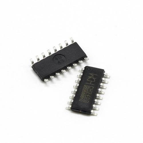
the package of ch340
CH340 has a variety of packaging methods, including CH340R, CH340T, CH340G. Each packaging method is slightly different, and its functions are also different.
CH340T: Under the Windows operating system on the computer side, the driver of CH340T can emulate a standard serial port and can perform serial port operations. It is fully compatible with most of the original serial port applications and usually does not require any modification. CH340T can be used to upgrade the original serial peripheral equipment, or to add additional serial ports to the computer through the USB bus. By adding level conversion devices, it can further provide RS232, RS485, RS422 and other interfaces.
CH340R: CH340R provides a 9-wire serial port with reverse polarity and supports IrDA. But it has no built-in crystal oscillator.
CH340G:CH340G provides a full 9-wire serial port without a built-in crystal oscillator.
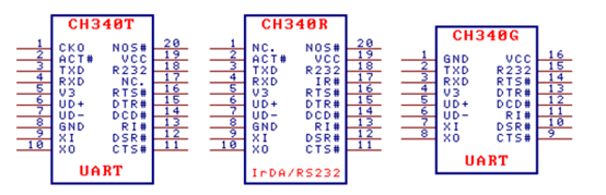
The pin function of CH340G
Pin 1:The common terminal is grounded and directly connected to the ground wire of the USB bus.
Pin 2:Serial data output.
Pin 3:Serial data input, built-in controllable pull-up and pull-down resistors.
Pin 4:When the power supply voltage is 3.3V, connect VCC to input external power;
When the power supply voltage is 5V, an external decoupling capacitor with a capacity of 0.1uF;
Pin 5:This pin is directly connected to the USB D+ data line.
Pin 6:This pin is directly connected to the D-data line of the USB.
Pin 7:This pin is the input terminal for crystal oscillation, which requires an external crystal and capacitor.
Pin 8:This pin is the output terminal of the crystal oscillator, which requires an external crystal and capacitor.
Pin 9:MODEM contact input signal, clear to send, low (high) effective.
Pin 10:MODEM contact input signal, data device is ready, low (high) effective.
Pin 11:MODEM contact input signal, ringing indicator, low (high) effective.
Pin 12:MODEM contact input signal, carrier detection, low (high) effective.
Pin 13:MODEM contact output signal, data terminal is ready, low (high) effective.
Pin 14:MODEM contact output signal, request to send, low (high) effective.
Pin 15:Auxiliary RS232 enable, high level effective, built-in pull-down resistor.
Pin 16:The positive power input terminal requires an external 0.1uF power decoupling capacitor.
Schematic diagram of CH340 module circuit
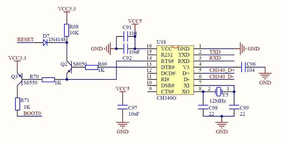
The TXD pin of H340 should be connected to the RXD pin of the microcontroller, and the RXD pin should be connected to the TXD pin of the microcontroller.
In addition, connecting a diode at the TXD pin and a resistor at RXD are both to prevent the USB from supplying power to the target chip.
In the above picture, a toggle switch is used to control the power supply of the microcontroller, so that the power supply can be disconnected when unnecessary.
Precautions:
1. CH340 has a built-in power-on reset circuit.
2. The CH340 chip needs to provide a 12MHz clock signal to the XI pin when it works normally. Generally, the built-in inverter of CH340 can generate clock signal through stable oscillation of crystal frequency. The peripheral circuit only needs to connect a 12MHz crystal between the XI and XO pins, and connect the XI and XO pins to the ground respectively with an oscillation capacitor.
3. CH340 chip supports 5V DC voltage or 3.3V DC voltage. When using 5V power supply, the VCC pin of the CH340 chip is connected to an external 5V power supply. At this time, the V3 pin should be connected to an external power supply decoupling capacitor with a capacity of 4700pF or 0.01uF. When using 3.3V power supply, the V3 pin of the CH340 chip should be connected to the VCC pin, and the external 3.3V power supply of 4700pFnd should be input at the same time, and the working voltage of other circuits connected to the CH340 chip cannot exceed 3.3V.
4. CH340 automatically supports USB device suspension to save power consumption. However, when the NOS# pin is low, the USB device is prohibited from suspending. In asynchronous serial port mode, the pins of the CH340 chip include: data transmission pins, MODEM contact signal pins and auxiliary pins. The data transmission pins include: TXD pin and RXD pin. If the R232 pin is high to enable the auxiliary RS232 function, the inverter will automatically insert the RXD pin, which is low by default.
5. MODEM contact signal pins include: CTS# pin, DSR# pin, RI# pin, DCD# pin, DTR# pin, RTS# pin. All these MODEM communication signals are controlled by computer applications and define their uses.
6. IR# pin is low to enable infrared serial port mode. When R232 is high, the RXD pin input is automatically reversed. The ACT# pin is the status output of the USB device configuration completion (for example, the USB infrared adapter is ready). IR# and R232 pins are checked only once after power-on reset.
7. Serial data includes 1 low-level start bit, 5, 6, 7 or 8 data bits, 1 or 2 high-level stop bits, and supports odd/even/mark/blank check Test. The baud rate error of the serial port sending signal is less than 0.3%, and the allowable baud rate error of the serial port receiving signal is not less than 2%.
8. Under the Windows operating system on the computer side, the CH340 driver can simulate a standard serial port, so under normal circumstances, most of the original serial port applications are completely compatible.
9. CH340 can be used to upgrade the original serial peripherals, or add additional serial ports to the computer through the USB bus. By adding level conversion devices, you can further provide RS232, RS485, RS422 and other interfaces.
CH340G is very important in PCB. Seeed Fusion has a powerful component library, which can complete PCB assembly as quickly as possible.