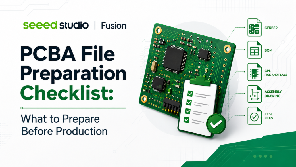
PCBA File Preparation Checklist: What to Prepare Before Production
🔍Why File Preparation Matters Before PCBA
In PCBA manufacturing, many delays can be traced back to the file review stage before production begins.
A complete file package helps manufacturers quote, source, assemble, inspect, and test your project more smoothly. If the BOM, Gerber, CPL, assembly drawing, or test instructions are incomplete or inconsistent, the project may enter repeated confirmation loops.
Use this guide as a quick checklist before submitting your PCBA files.
📋Quick Checklist
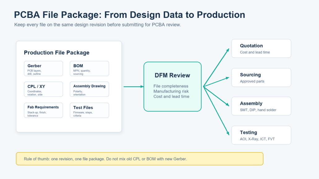
Before submitting a PCBA project, prepare the following files:
| File | Main Purpose | Key Checks |
|---|---|---|
| Gerber | Transfers PCB graphics, stack-up, drill, solder mask, and silkscreen manufacturing data | Includes traces, solder mask, drill files, board outline, silkscreen layers, board size, revision, and date |
| BOM | Defines all components, quantities, packages, MPNs, manufacturers, and sourcing information | MPN, package, quantity, reference designators, alternatives, and customer-supplied parts are clear |
| CPL / Pick-and-Place File | Defines component coordinates, rotation, and assembly side for pick-and-place programming | Coordinates, rotation, Top/Bottom side, and reference designators match the BOM and assembly drawing |
| Assembly Drawing | Helps production and quality teams verify component position, direction, and polarity | Polarity marks, orientation, reference designators, insertion side, and double-sided information are accurate |
| Schematic | Supports failure analysis, debugging, and functional issue diagnosis | Includes revision and date, and matches the current PCB/BOM |
| Test Firmware & Test Guideline | Supports programming, ICT/FVT, functional testing, and traceability | Firmware version, programming method, test steps, and pass/fail criteria are complete |
| PCB Fabrication Requirements | Defines board thickness, copper thickness, impedance, material, surface finish, and other process parameters | Parameters are reasonable and do not unnecessarily affect cost, yield, or lead time |
1. Gerber
Gerber files are the standard production files used to manufacture the PCB. They help the manufacturer read the board layers, drill holes, paste layers, and board outline.
👇 Before submitting Gerber files, use a Gerber Viewer to check three things
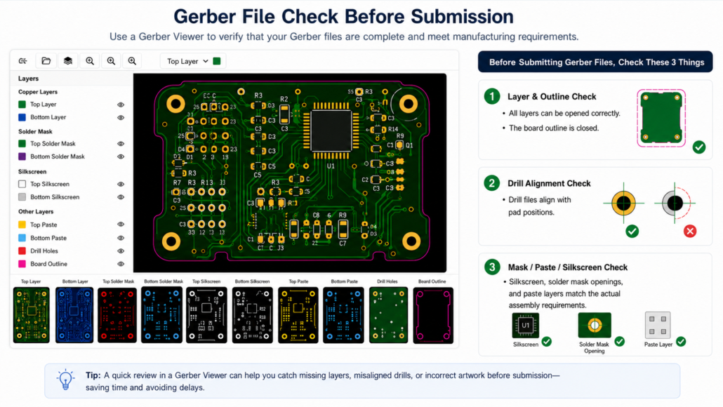
Special Requirements?
For special PCB requirements, such as impedance control, V-CUT, gold finger beveling, special outline, ENIG thickness, high-TG material, or board thickness tolerance, add them to the fabrication notes or PCB requirements file instead of mentioning them only by email.
When preparing Gerber files, always export them from the latest PCB revision and verify the layers before submission.
👉Quick export steps for KiCad, Fusion 360, and Altium Designer
2. BOM
The BOM tells the manufacturer what components need to be sourced and assembled. For Seeed Fusion PCBA orders, please follow the BOM template so the system can read the file correctly.
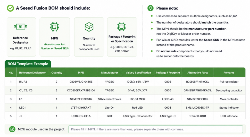
The following is a BOM template for reference:
* Note: The BOM, CPL, and Assembly Drawing should come from the same design revision. If one file is outdated, placement programming, first-article inspection, or AOI setup may be affected.
3. CPL / Pick-and-Place File
The CPL file provides component placement data for SMT assembly, including designator, X / Y coordinates, rotation, side, package, and value.
Make sure the CPL matches the BOM and assembly drawing. Outdated coordinates or incorrect rotation settings can cause placement errors during production.
4. Assembly Drawing
The Assembly Drawing is an important reference for PCBA production and quality inspection. It helps production and QC teams verify component placement, orientation, polarity, and insertion direction during SMT first-article inspection, IPQC, repair analysis, and manual checks.
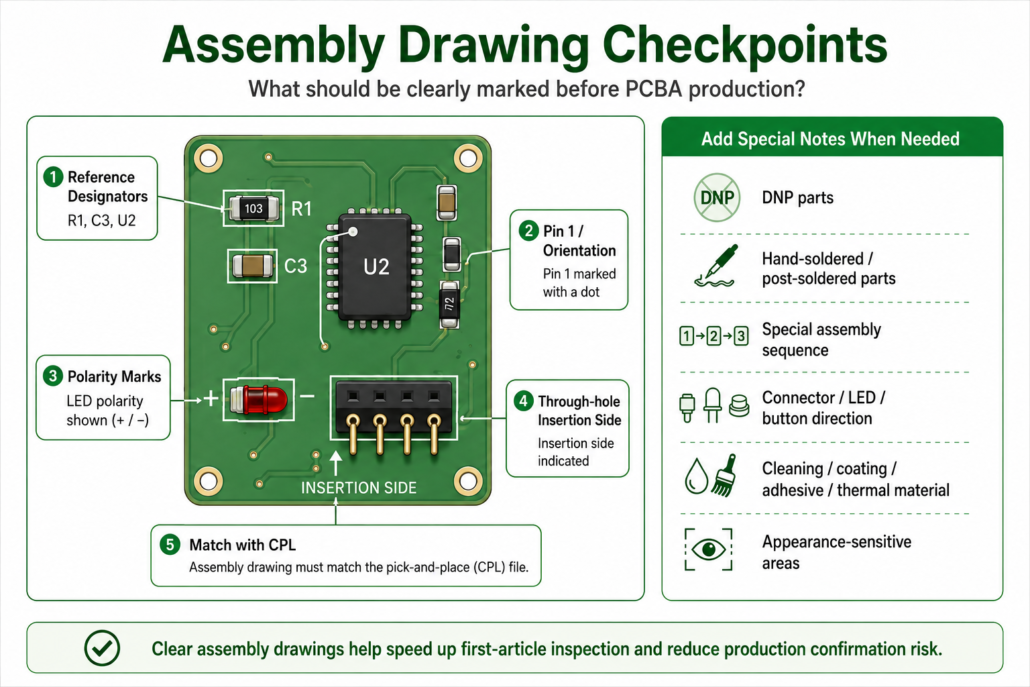
Common issues include missing polarity marks, unclear through-hole insertion direction, and mismatch between the Assembly Drawing and CPL / coordinate file. These issues may look minor in design files, but they can slow down first-article inspection and production confirmation.
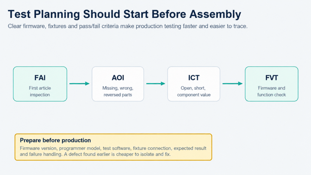
5. Test Requirements
PCBA file preparation should also include test requirements. Clear test firmware, test instructions, and pass/fail criteria help identify defects earlier and reduce repair costs.
Common PCBA tests include:
- AOI: Checks missing, wrong, reversed parts, and visible soldering defects.
- ICT: Checks shorts, opens, solder issues, and basic electrical performance through test points.
- FVT: Verifies product functions based on customer test requirements, and may include firmware programming.
Testing should be planned before production. If test firmware and production firmware are different, clearly mark their versions and purposes to avoid traceability and verification risks.
Test Files You Should Prepare
| File | Recommended Content |
| Test Firmware | Firmware file, version number, development date, applicable hardware revision |
| Programming Guide | Programmer model, connection method, programming software, programming steps |
| Test Guideline | Test environment, test fixture, test steps, pass/fail criteria |
| Expected Result | LED status, serial output, voltage range, communication result, screen display, etc. |
| Failure Handling | Common failure symptoms, retest method, abnormal sample handling |
If test firmware and production firmware are different, clearly distinguish their versions and purposes. Otherwise, production traceability, repair analysis, and outgoing verification may carry additional risk
✅Testing files are an important part of the overall PCBA file package. Along with design and manufacturing files, they should be prepared in a consistent revision before submission. The diagram below shows how a complete file package supports DFM review and the downstream production process.
🔥Have your complete PCBA file package ready?
Start your project with Seeed Fusion and move smoothly from DFA review to quotation, sourcing, assembly, and testing.
❓If you have any other questions, feel free to contact us at [email protected]
📍FAQ
1. Can I start a PCBA quotation with only Gerber and BOM files?
They can be used for an initial evaluation, but they are not recommended as a complete production file package. Without CPL, assembly drawing, and test instructions, placement, first-article inspection, and test confirmation will require additional communication.
2. Are both CPL and Assembly Drawing required?
If the project is for PCBA production, yes, both are required. The CPL is mainly used for pick-and-place programming, while the Assembly Drawing helps engineering and quality teams verify component position, orientation, and polarity. They serve different purposes and complement each other.
3. Can the BOM include only specifications without MPNs?
Strongly not recommended. Descriptions such as “10k resistor” or “0.1uF capacitor” make sourcing and alternative-part decisions unclear. For key components, ICs, connectors, modules, and certification-related parts, provide the full MPN and manufacturer whenever possible.
4. When should test instructions be provided?
Whenever the PCBA requires programming, communication, sensor reading, power measurement, display, buttons, wireless functions, or system-level integration, test instructions should be provided. The earlier the test method is defined, the easier it is to detect design or process risks before production.
5. What if some process parameters are uncertain?
You can first provide product function, application scenario, and key constraints, such as cost priority, reliability priority, impedance control, high-temperature environment, or appearance requirements. The Seeed Fusion engineering team can help evaluate more suitable PCB process parameters during DFM review.