Giving Soil a “CT Scan”: Soil Moisture Sensors Explained
From single-point probes to multi-depth profiles, explore the different sensor designs and connectivity options behind smart agriculture.
This article is part of the Weather Sensor Know-How series: practical guides to the technologies behind environmental monitoring, smart agriculture, and microclimate applications. See all guides.
For generations, farmers have worked at the mercy of the weather, relying on experience to decide when to irrigate and fertilize. Picking up a handful of soil, squeezing it, and feeling its texture offered practical clues about moisture and growing conditions.
Today, smart agriculture adds another set of “senses” to the field.
Buried in the soil, temperature, moisture, and electrical conductivity sensors act like round-the-clock health monitors beside crop roots. They track the root zone’s “body temperature,” water content, and electrical conductivity, or EC, turning hidden soil conditions into data that can support precision irrigation and better-informed fertilizer management.
EC needs a little explanation. It indicates how readily the soil conducts electricity and can provide useful information about dissolved salts. It is not, however, a direct measurement of individual nutrients or overall soil fertility.
As the Internet of Things (IoT) develops, soil-monitoring devices are becoming increasingly diverse in both physical design and connectivity.
Some have short steel prongs. Others arrange several sensing elements along a vertical frame. Still others hide their sensing components inside a long protective tube.
What explains these different shapes? And how do you choose the right combination for your field?
Let’s look beneath the surface.
1. Soil Sensor Designs: From Single-Point Readings to Multi-Depth Profiles
A sensor’s physical structure affects more than how easily it can be installed. It also determines which part of the soil it measures, how representative that reading is, and how effectively the sensing elements interact with the surrounding soil.
Good soil contact is particularly important. A small air gap may seem insignificant, but it can change the electrical response around a probe and introduce measurement errors.
Single-Point Prong Sensors: Focused Measurement at One Depth

Structure and measurement principle
These sensors typically consist of two to four 316L stainless steel probes and a body encapsulated in high-density epoxy resin.
Once inserted into the soil, the probes act as the electrodes of a parallel-plate capacitor or form a high-frequency transmission line, depending on the sensing design. Changes in the surrounding soil’s electrical properties allow the sensor to estimate moisture content.
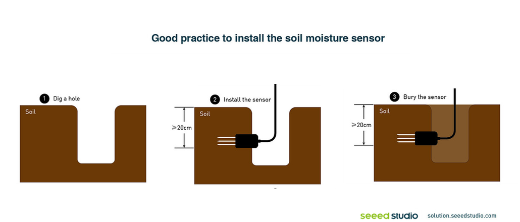
(For accurate soil monitoring, install the single-layer soil sensor in the root zone. A depth of 20 cm is only an estimate; the ideal installation depth depends on the crop and its root system.)
Key advantages
The steel prongs can be inserted firmly into undisturbed soil, providing close contact and reducing the air gaps that can distort measurements. Good contact also helps reduce interface-related impedance effects where these are relevant to the measurement method.
This design can respond quickly to short-term moisture changes in the upper soil layers. To monitor deeper conditions, individual sensors can be installed at the required depths.
Limitations
A single-point reading represents only a limited volume of soil. One probe cannot reveal the full pattern of water and salt infiltration, accumulation, and movement through the soil profile.
However, this does not mean single-point sensors are unsuitable for multi-depth monitoring. Installing additional probes at different depths creates a flexible way to build that vertical picture.
Multi-Depth Prong Sensors: Independent Measurements at Several Levels
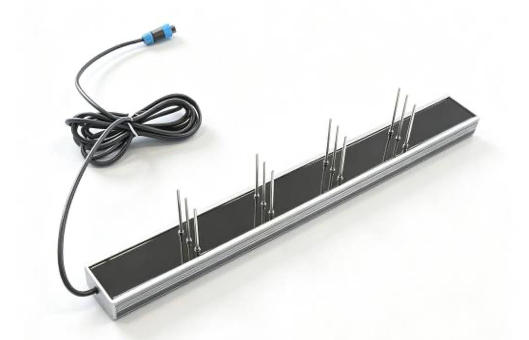
Structure
Multi-depth prong sensors use a rigid vertical support carrying several sets of independent two- or three-prong electrodes.
These electrodes are positioned at defined depths—for example, 10, 20, and 40 cm—so that different soil layers can be monitored through one assembly.
Key advantages
With a well-designed sensing arrangement, each layer can be measured with limited electromagnetic interference from the others.
This makes it possible to observe changes at different depths, including the layers where root water uptake is most active and where evaporation may concentrate dissolved salts.
Instead of asking only, “Is the soil wet?”, a multi-depth sensor helps answer a more useful question: “Which part of the soil profile is wet—and how is that changing?”
Limitations
Installing this type of assembly may require excavating a soil-profile pit to position the electrodes correctly.
That can substantially disturb the soil’s natural structure. Careful installation and backfilling are therefore important when interpreting the measurements that follow.
Multi-Depth Tubular Sensors: Profile Monitoring with Less Excavation
Structure
Multi-depth tubular sensors typically use a corrosion-resistant PVC or fiberglass tube as the outer housing.
Inside the tube, several ring-shaped capacitive sensing electrodes are arranged at fixed intervals along its length. These provide repeated measurements at several defined depths.
Key advantages
- Less disruptive installation. A dedicated soil auger creates a closely fitted hole into which the sensor is inserted, or screwed where the design requires it. There is no need to excavate a large pit, helping preserve more of the original soil structure.
- Protected internal components. The circuitry and sensing electrodes are enclosed within the tube rather than exposed directly to the soil. With suitable housing materials and sealing, this helps protect the internal components from moisture and corrosive soil conditions.
- Multi-depth observations. Measurements from several levels help reveal how water moves through the root zone and into deeper soil.
Limitations
Installation quality is critical. If an air gap remains between the tube wall and the surrounding soil, the sensor may report substantially lower moisture content than is actually present.
The goal is not simply to make a hole and insert the tube. It is to establish the soil contact required by the manufacturer’s installation procedure.
Also, “multi-depth” does not necessarily mean measurement at every point along the tube. These sensors generally provide ongoing readings at discrete sensing depths.
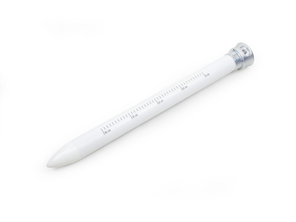
Seeed Studio’s multi-depth tubular soil sensors illustrate this approach, combining an integrated waterproof, corrosion-resistant housing with measurements at several depths, such as 20, 30, and 40 cm, depending on the configuration.
RS-485 configurations support wired connections to compatible PLCs or data loggers, while 4G-enabled configurations provide a route to remote cloud access without a local gateway. Cellular operation still requires compatible coverage, a data service, and appropriate setup.
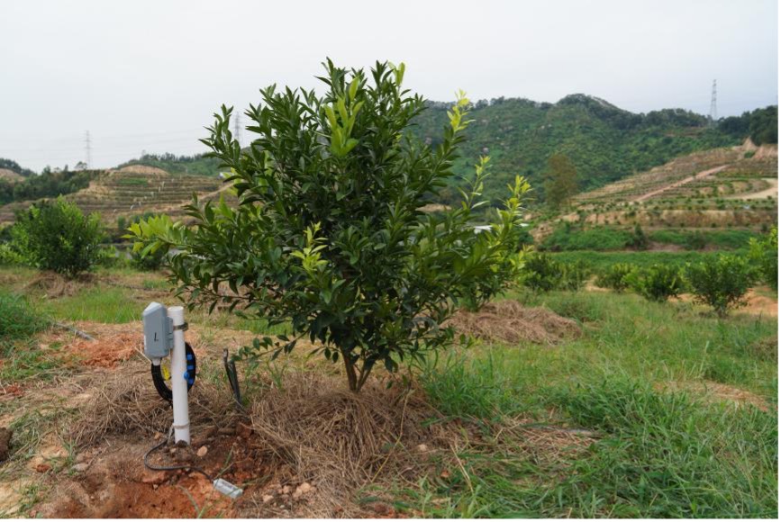
2. Connectivity: Choosing Between RS-485, 4G, and LoRaWAN
Once the sensing elements collect data, the communication architecture determines how those readings reach a controller, data platform, or farm-management system.
This choice affects deployment cost, power consumption, and long-term maintenance.
RS-485: Stable Wired Communication
RS-485 is a wired communication interface commonly used with the Modbus RTU protocol.
It offers stable communication, good resistance to electrical interference when properly installed, and relatively economical integration with compatible equipment.
The main trade-off is cabling. Every monitoring point needs a suitable wired connection, making this approach particularly useful for clustered installations, greenhouses, laboratories, and sites with existing control infrastructure.
RS-485 carries data between devices; remote cloud access requires a connected logger, gateway, or other communication equipment.
4G Cellular: Connecting Dispersed Monitoring Sites
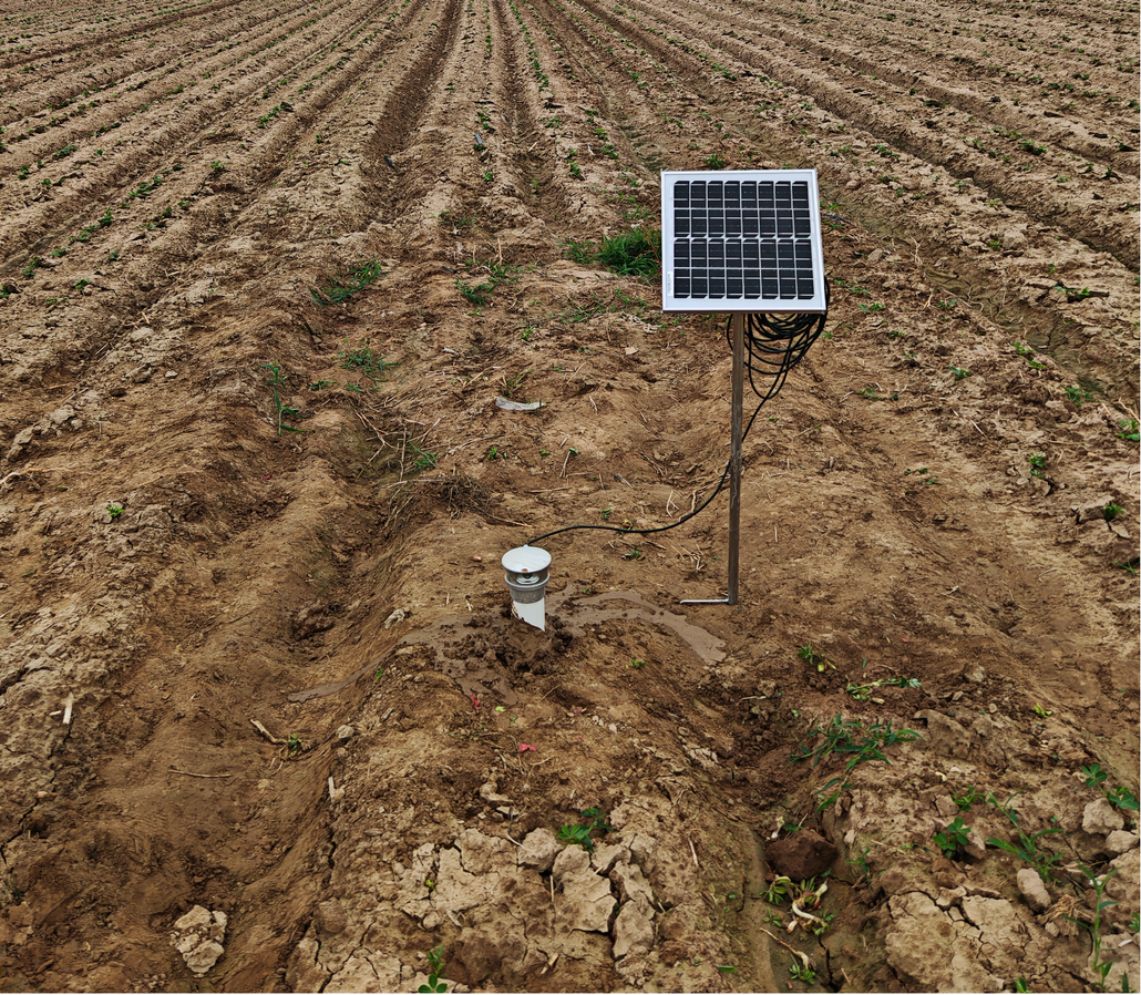
A device with an integrated 4G module can upload measurements through a cellular network, removing the need to install a local gateway.
This can make deployment convenient when monitoring points are widely scattered—for example, across separate open fields or orchards.
The attraction is straightforward: install the device, configure the connection, and make the readings available remotely.
The practical requirements are equally important. Cellular coverage, supported network bands, power availability, SIM provisioning, and ongoing data charges all need to be considered.
LoRaWAN: Long-Range, Low-Power Monitoring
LoRaWAN connects sensor devices to one or more gateways, which forward their messages to a network server and application platform.
This is a star-of-stars architecture—not a mesh in which sensors relay messages through one another.
Battery-powered devices can spend much of their time asleep, waking to measure and transmit at configured intervals. Depending on the hardware, sleep current may be in the microamp range.
The result is a combination well suited to distributed agricultural monitoring:
- Long communication range under suitable conditions.
- Low device power consumption.
- Extended battery operation.
- Shared gateway coverage for multiple monitoring points.
However, LoRaWAN is not a network that deploys and maintains itself. Gateway coverage, backhaul, device provisioning, reporting intervals, and radio conditions still require planning.
What Does This Mean in the Field?
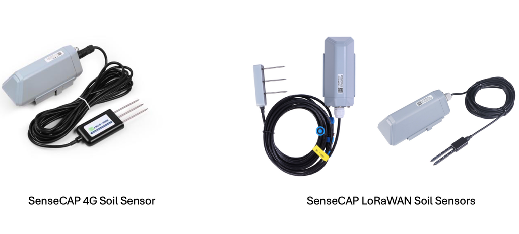
The single-point 4G-MTEC-01 soil sensor combines a soil probe with a 4G communication module, making it a practical configuration for dispersed open-field locations where installing a shared local gateway may be inconvenient.
For a large farm with centrally managed monitoring points, a LoRaWAN device such as the SenseCAP S2108 offers a different approach. It combines soil moisture, temperature, and pore EC measurement with low-power wireless connectivity.
Under suitable conditions, one gateway can serve dozens of monitoring points across several kilometers. Battery life may range from one to three years, depending on the device configuration, reporting interval, radio conditions, and operating environment.
The choice is therefore not simply “Which wireless technology is better?”
It is “Which network makes sense for the way this farm is laid out?”
3. Soil Moisture Sensor Comparison: Matching Design and Connectivity
The following table brings the physical and communication choices together.
Sensor accuracy should be assessed from the specific product’s specifications, calibration, soil conditions, and installation—not inferred from its shape or communication protocol alone.
| Sensor design | Connectivity | Main advantages | Limitations and considerations | Recommended applications |
| Single-point prong sensor | RS-485 | Close soil contact, responsive measurements, and economical wired integration | Measures a limited soil volume; requires field cabling | Greenhouse seedling production, container plants, and laboratory soil studies |
| Single-point prong sensor | 4G | Responsive local measurements with cellular data upload; no local gateway required | Single-point coverage; requires cellular service and associated data charges | Dispersed open fields, remotely managed farms, and orchards where cabling is impractical |
| Single-point prong sensor | LoRaWAN | Long-range, low-power communication; multiple devices can share gateway coverage | Requires suitable LoRaWAN coverage and gateway backhaul | Farms with multiple monitoring locations and centrally managed wireless infrastructure |
| Multi-depth prong sensor | RS-485 | Close electrode contact and separate measurements at several depths | Installation may require a soil-profile pit, disturbing the natural soil structure | Deep-rooted fruit crops such as apple and citrus, and studies of water and solute movement in wheat or maize fields |
| Multi-depth tubular sensor | RS-485 or 4G-enabled configuration | Less disruptive installation, ongoing multi-depth monitoring, and protected internal components | Requires careful installation to avoid air gaps; cost varies with configuration | Root-zone profile monitoring and long-term observation of water movement in fields and orchards |
4. Build a Soil-Monitoring Network That Fits the Field
Soil monitoring is more than pushing a probe into the ground. It requires matching the sensing structure to the communication architecture—and matching both to the crop and the site.
Single-point prong sensors offer cost-effective, flexible placement. Multi-depth prong sensors help reveal how water and salts change between soil layers. Tubular sensors combine a protected structure with a less disruptive approach to profile monitoring.
Each design has a useful role under the right conditions.
The most suitable choice depends on the farm’s terrain, crop rooting depth, soil conditions, and communication environment. A shallow-rooted crop in a greenhouse does not necessarily need the same monitoring arrangement as a deep-rooted orchard spread across several remote sites.
As agricultural IoT continues to develop, a well-planned network can connect observations from the upper soil layers, through the root zone, and into deeper soil.
That gives growers more than a collection of numbers. It gives them a clearer basis for deciding when to irrigate, how deeply water is penetrating, and whether water or dissolved salts are moving beyond the intended zone.
The goal is not to discard experience. It is to strengthen it with evidence—helping every application of water and fertilizer serve a clearer purpose, while reducing waste and supporting more sustainable production.
Explore Further
Planning a soil-monitoring project? Start with the depths you need to observe, the variability across your field, and the connectivity available on site. Let us know your application scenario and go-to choice of soil sensor design (single-layer vs. multi-layer; wired vs. wireless).
Browse the SenseCAP sensor catalog (PDF) to compare available approaches, or contact [email protected] to discuss which configuration might fit your application.
Read More from the Sensor Know-How Series
- Solar Radiation Sensors Explained: Thermopile vs. Photodiode
- Why Temperature Sensors Need a Solar Radiation Shield for Accurate Measurements
- Two Technologies for Wind Monitoring: Cup-and-Vane vs. Ultrasonic Sensors
- NDIR CO2 Sensor Explained: How Infrared Gas Sensing Works
- Doppler Radar Precipitation Sensor: How Can It Measure Rain Without a Funnel?
- 2026 Climate Reality Check: When Extremes Become the Norm, How Do We Adapt?
About Author
