Mobile Robot Full-stack Development In Practice Ⅳ: How Does a Robot Understand What It Sees? YOLO, ByteTrack, SegFormer & FoundationPose
From object detection and multi-object tracking to semantic segmentation and 6D pose estimation on NVIDIA Jetson with ROS 2.
In Part III, we looked at how a mobile robot estimates its motion by bringing LiDAR, IMU, wheel feedback and GNSS into a consistent sensor-fusion workflow. But knowing how the robot is moving is only part of the picture. It also needs to interpret what its cameras observe: identify objects, keep their identities across frames, distinguish relevant regions, and estimate the pose of objects it needs to interact with.
A detection box, a track ID, a pixel-level class map and a 6D pose are different kinds of information. Each answers a different question, relies on different inputs and needs its own validation. This Module 04 guide follows the AI-perception experiments on reComputer Robotics J501, focusing on how model outputs are inspected and passed into ROS 2 interfaces that other robot components can use.
What you will learn:
- Deploy YOLO11 with TensorRT and verify detection boxes, coordinates and ROS 2 messages.
- Use ByteTrack to maintain object identities across frames and investigate ID changes.
- Use SegFormer to interpret pixel-level classes and derive a task-specific ground-candidate mask.
- Estimate a known object’s 6D pose from recorded RGB-D data with FoundationPose, then understand the transform into the robot frame.
Before you start: basic familiarity with ROS 2 topics, terminal commands and the earlier Jetson development environment will help. You do not need to run all four experiments at once; each section can be explored and validated independently.
If this is your first time joining the series, start with the course introduction for the complete learning roadmap. You can also revisit Part I: the Jetson and ROS 2 development foundation, Part II: camera integration and calibration, and Part III: LiDAR, IMU and sensor fusion. The open-source course repository contains the full documentation, code and updates.
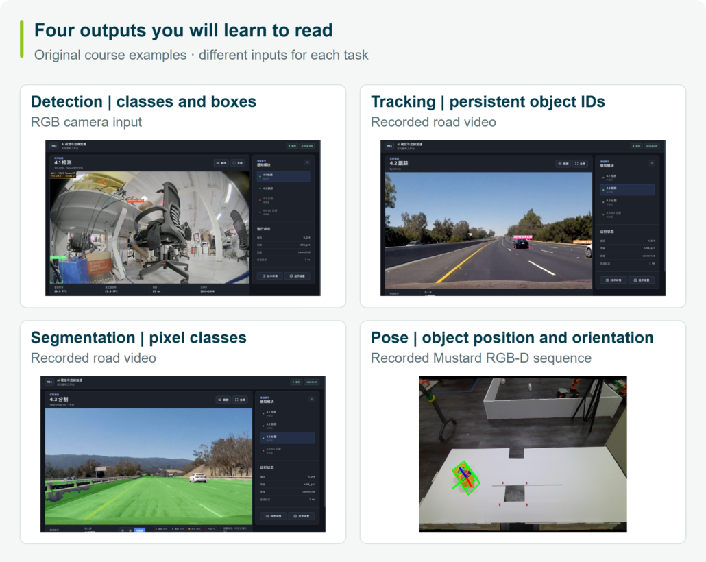
Start with the outputs. The examples below show what each experiment produces. Keep the input fixed and learn to explain each result before adding another component.
Jump to: YOLO deployment · Object tracking · Segmentation · 6D pose · Course code
Match the Perception Task to the Information You Need
Imagine a robot entering a work area. It may need to identify nearby objects, keep observing one as it moves, distinguish ground from surrounding regions, or determine the position and orientation of a known part. These requirements lead to different tasks:
- Object detection — YOLO: predict classes, 2D boxes and confidence scores from an RGB image. The course deploys the model through PyTorch, ONNX and TensorRT, then publishes detections as ROS 2 messages.
- Multi-object tracking — ByteTrack: associate detections across frames using motion prediction and matching, assigning persistent track IDs.
- Semantic segmentation — SegFormer-B0: predict a class for every pixel, then select configured classes to form a ground-candidate mask.
- 6D pose estimation — FoundationPose: combine RGB-D, camera intrinsics, a target-instance mask and a CAD mesh to estimate a known object’s 3D translation and rotation in the camera frame.
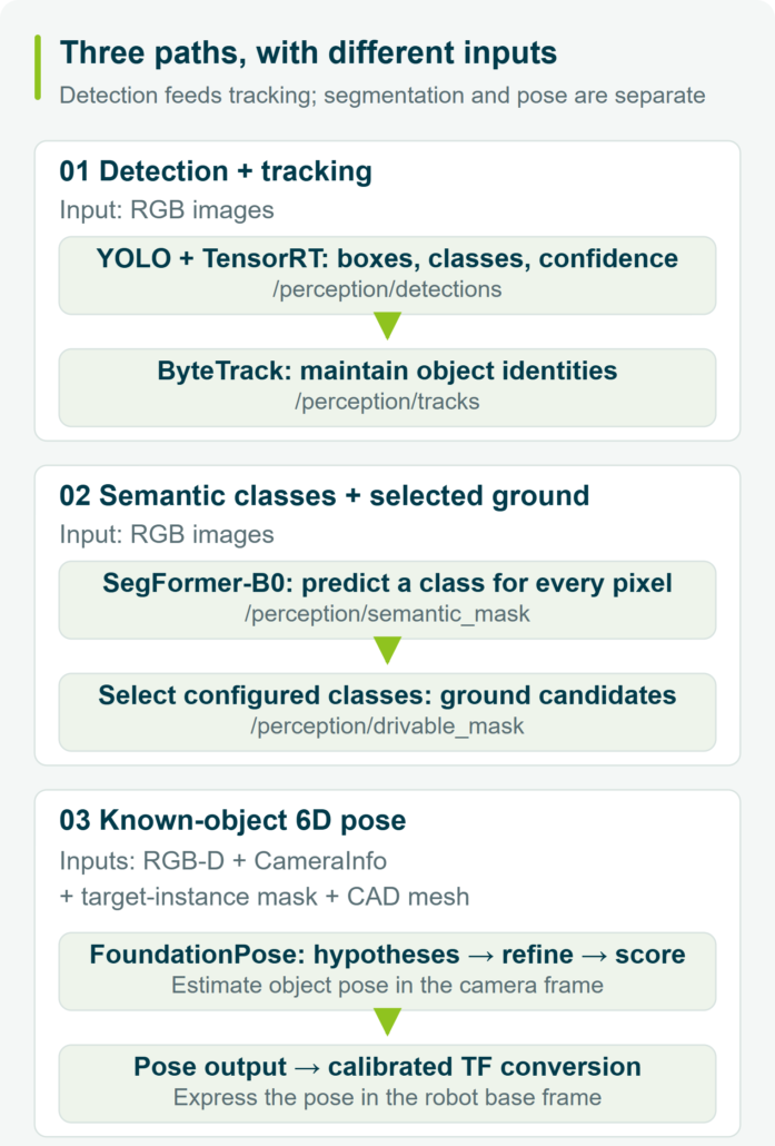
Three Distinct Perception Data Paths
Detection and tracking form one connected path: RGB images feed YOLO, its detections go to /perception/detections, and ByteTrack produces identified detections on /perception/tracks.
Segmentation runs independently on RGB images. SegFormer produces pixel classes on /perception/semantic_mask; a class-selection rule generates /perception/drivable_mask. Semantic labels do not identify individual object instances, and selected ground pixels do not establish that a robot can safely drive there.
Object pose requires RGB-D and CameraInfo, a mask for the particular target instance, and its mesh. FoundationPose generates pose hypotheses, refines them and scores candidates. A detection box or a semantic class mask is not a substitute for that instance mask. The resulting camera-frame pose needs a coordinate transform before use in the robot’s base frame.
The course offers two implementations of the pose task: NVIDIA Isaac ROS FoundationPose in M4.4 and native NVlabs FoundationPose in M4.5. They are different engineering routes, rather than consecutive models in one pipeline.
Prepare the Jetson Platform and Inputs
The course reference platform is Seeed reComputer Robotics J501 with NVIDIA Jetson AGX Orin 32GB. Match its documented environment before changing versions:
| Component | Course configuration |
|---|---|
| Hardware | reComputer Robotics J501 |
| JetPack / L4T | 6.2.1 / R36.4.4 |
| Ubuntu | 22.04 |
| ROS 2 | Humble |
| CUDA | 12.6 |
| TensorRT | 10.3.x |
| Isaac ROS | 3.2 |
| Python | 3.10 |
The front GMSL camera supplies images through /dev/video0. Pose exercises also use recorded RGB-D data; connecting a live RGB-D camera introduces additional alignment and synchronization work. The course previews below use different inputs: indoor detection, recorded road video for tracking and segmentation, and the Mustard RGB-D sequence for pose.
Install dependencies, build the workspace and prepare the model assets before launching an exercise. The repository does not contain every weight, engine or mesh. The maintained setup instructions and lesson links are collected in the course navigation at the end.
After that preparation, set the code-directory path for your checkout. New inspection terminals also need the ROS and workspace environments:
export M4_CODE_ROOT="$HOME/mobile-robot-full-stack-course/docs/M04-AI-Vision-And-Edge-Acceleration/code"
cd "$M4_CODE_ROOT"
source /opt/ros/humble/setup.bash
source "$M4_CODE_ROOT/ros2_ws/install/setup.bash"
For parameter comparisons, keep the input, resolution, model and configuration fixed. Change one setting at a time so that a new scene or camera geometry does not obscure the effect.
Deploy YOLO with TensorRT and Inspect Its ROS 2 Output
Understand the Candidates Before Filtering Them
The course’s YOLO11n COCO export takes a 640 × 640 image and returns [1, 84, 8400]: one batch, four box values plus 80 class scores, and 8,400 candidate locations from 80×80 + 40×40 + 20×20. Other models and export modes may use different output contracts.
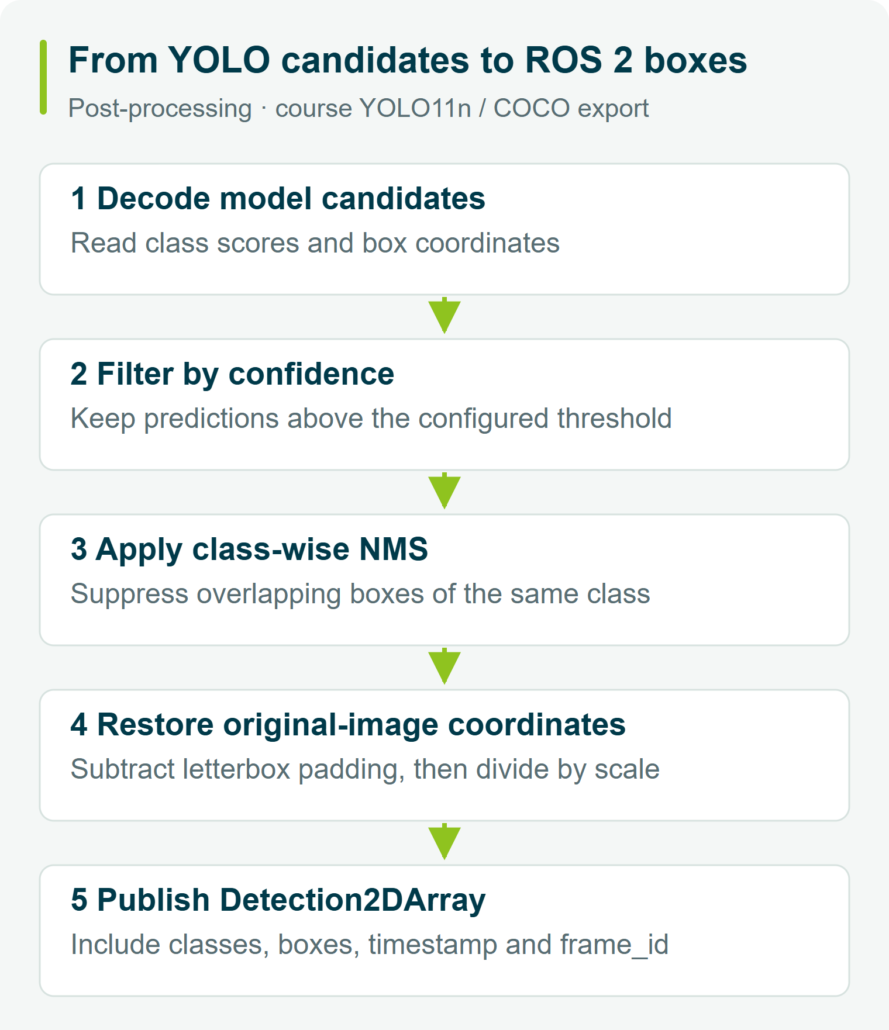
Post-processing reads the class scores and box coordinates, filters low-confidence candidates, applies class-wise non-maximum suppression (NMS), and restores boxes to the original image. Confidence controls which predictions survive; the NMS IoU threshold controls duplicate suppression. A confidence of 0.8 is not an 80% measured accuracy rate.
With yolo11n.pt and the required dependencies prepared, export and build the engine:
yolo export model=yolo11n.pt format=onnx simplify=True dynamic=False
python3 -c "import onnx; onnx.checker.check_model(onnx.load('yolo11n.onnx'))"
/usr/src/tensorrt/bin/trtexec \
  --onnx=yolo11n.onnx \
  --saveEngine=yolo11n_fp16.engine \
  --fp16 --memPoolSize=workspace:4096
These steps export a static graph, check its structure and build an FP16 engine for the course’s TensorRT 10.3 environment. They do not retrain the detector. Place the engine and labels according to the node configuration, and recheck compatibility when changing hardware, runtime or export settings. Detecting objects outside the pretrained classes requires a separate data and training workflow.
Correct Class, Displaced Box? Check Letterbox Geometry
Letterbox preprocessing preserves aspect ratio and pads the image to the model input size. To map a predicted point back, subtract the padding first, then divide by the scale saved during preprocessing.
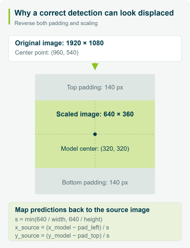
For example, 1920 × 1080 becomes 640 × 360, with 140 pixels above and below. The original center (960, 540) maps to (320, 320) in the padded input. Omitting the padding subtraction shifts the recovered box. Use the actual scale and padding saved during preprocessing, including rounding; also check BGR/RGB, normalization and HWC/NCHW layout.
Check the Message as Well as the Overlay
From the prepared code directory, start the detector:
./scripts/m4/run_m4_1_demo.sh
In another sourced terminal, inspect the interface and QoS, publishing rate, then the message itself:
ros2 topic info -v /perception/detections
ros2 topic hz /perception/detections
ros2 topic echo /perception/detections --once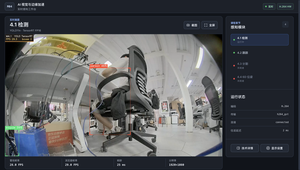
The output is vision_msgs/msg/Detection2DArray. Pair a message with its source image and check the class, box coordinates, acquisition timestamp and frame_id. A processed frame with no targets should still publish an empty detections array, allowing downstream tracking to distinguish an empty observation from a stopped input.
If a topic exists but a subscriber receives nothing, inspect QoS. The course uses BEST_EFFORT sensor publishing; a subscriber requesting RELIABLE delivery may be incompatible. For detection quality, use labeled data. Precision asks how many reported objects are correct; Recall asks how many real objects were found. Report mAP with the dataset and IoU convention so that comparisons remain meaningful. An overlay alone does not measure accuracy.
Track the Same Object Across Frames with ByteTrack
Detection supplies boxes for each frame. ByteTrack connects them to existing tracks: a Kalman model predicts motion, association matches observations, and track management handles creation, temporary loss and removal.
Its two-stage association first uses higher-score detections, then lower-score candidates to help recover some unmatched tracks. Those lower-score candidates must reach the tracker. The course’s detector confidence and tracker activation defaults are both 0.25; upstream filtering can remove the candidates needed by the second stage.
Stop the standalone detection demo before running the tracking entry point, which starts its required detection/tracking pipeline:
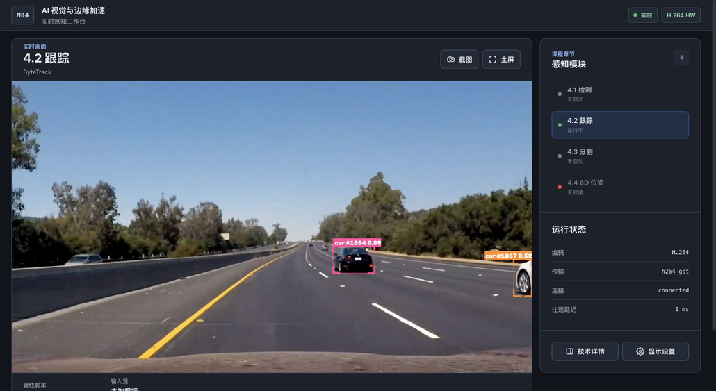
./scripts/m4/run_m4_2_demo.sh
Check /perception/tracks in another sourced terminal. It remains a Detection2DArray, now carrying track IDs in Detection2D.id.
Tune One Failure, Then Replay the Same Sequence
The course configuration includes:
track_activation_threshold: 0.25
lost_track_buffer: 90
minimum_matching_threshold: 0.8
frame_rate: 30
minimum_consecutive_frames: 1
Increasing minimum_consecutive_frames delays confirmation and can filter short-lived false tracks. lost_track_buffer controls how long a missing track remains available. The library calculates that window as int(frame_rate / 30.0 * lost_track_buffer): these settings give 90 processed frames, roughly three seconds at an actual 30 FPS or six at 15 FPS if the configuration stays unchanged.
In Supervision 0.27.0, minimum_matching_threshold is a first-stage matching-cost ceiling. Increasing it allows higher-cost matches; it is not a minimum IoU threshold.
Replay a fixed sequence with entry, occlusion and exit. Note when detections disappear and when IDs change, then compare one parameter adjustment. Some node parameter updates rebuild the tracker and reset IDs; separate that reset from an identity switch during normal operation. This route does not enable ReID or global camera-motion compensation, and it does not automatically use the previous module’s IMU or odometry.
Use SegFormer to Separate Pixel Classes from Ground Candidates
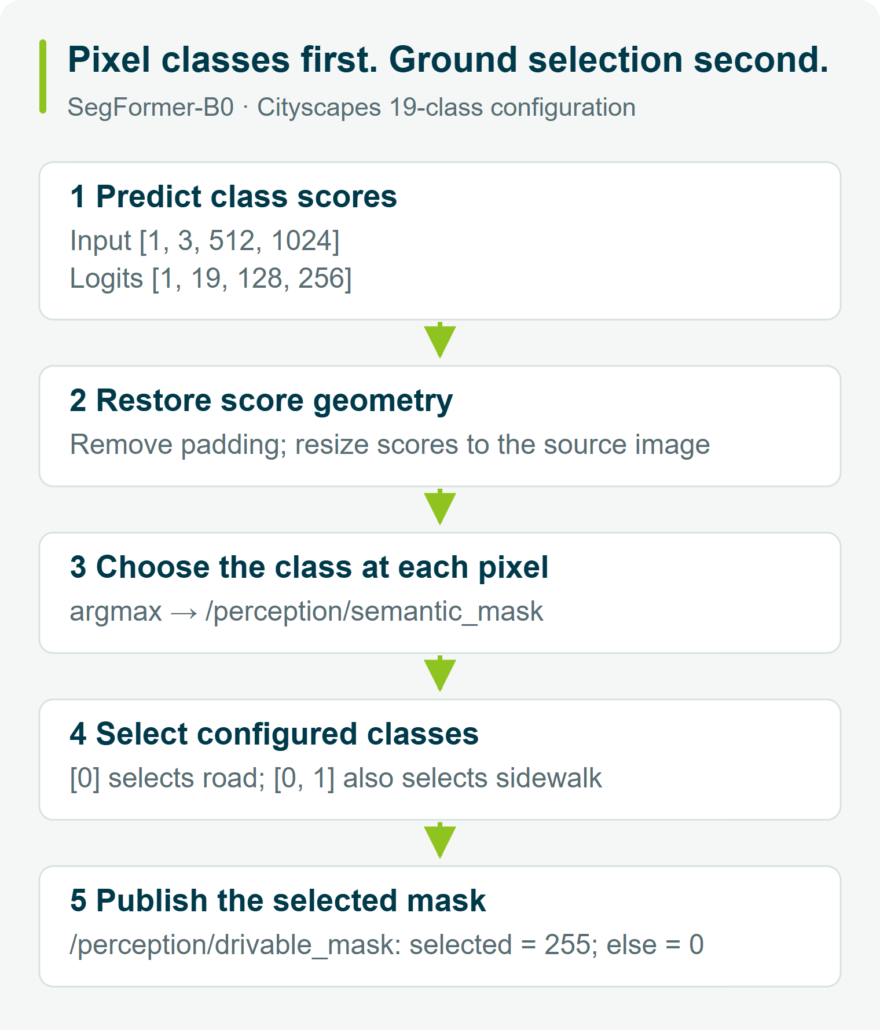
SegFormer-B0 predicts a class at each pixel. The course configuration takes [1, 3, 512, 1024] input and returns [1, 19, 128, 256] logits for 19 Cityscapes classes.
The important order is restore score geometry, then choose the class. Remove letterbox padding and resize the class scores to the original-image geometry before applying pixelwise argmax. Choosing labels first and enlarging them can produce different boundaries because it propagates decisions already made.
The node publishes two outputs:
/perception/semantic_mask: predicted class IDs./perception/drivable_mask: configured classes written as255, with other pixels set to0.
The default drivable_class_ids: [0] selects road. Adding class 1 includes sidewalk; it changes the selection rule, not the model weights or semantic predictions.
Prepare the segmentation engine, stop other demo modes, then run:
./scripts/m4/run_m4_3_demo.sh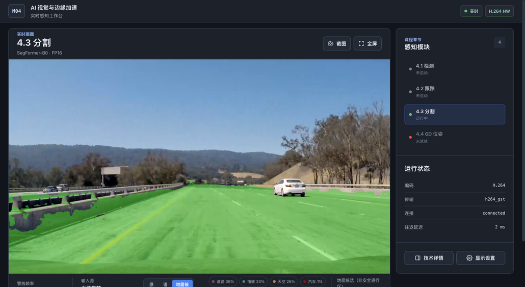
For a useful experiment, keep one road/sidewalk frame fixed and compare selections [0] and [0, 1]. The semantic map should stay the same while the selected mask changes. A displaced boundary points toward geometry restoration; a wrong class points toward the model and scene; a correct class selected for the wrong purpose points toward the mapping.
Evaluation needs labeled pixels from the target scene. If 80% of an image is road, predicting road everywhere still gives 80% Pixel Accuracy while missing every other class. Use per-class IoU, mIoU and a confusion matrix to expose that failure.
Estimate a Known Object’s 6D Pose with FoundationPose
A 2D detection cannot provide a known object’s full position and orientation. FoundationPose’s model-based route uses aligned RGB-D, camera intrinsics, a target-instance mask and a mesh. Keep the frame, mask, object dimensions and depth units consistent.
Start with the native Mustard recorded-data exercise. It lets you inspect the estimator before introducing live-camera synchronization and ROS transport. Prepare the documented NVlabs checkout, refiner/scorer weights and sample assets first.
Register Once, Then Update the Pose
First-frame register generates hypotheses, refines them against the observation and scores candidates. Later track_one calls start from the previous pose and perform local updates:
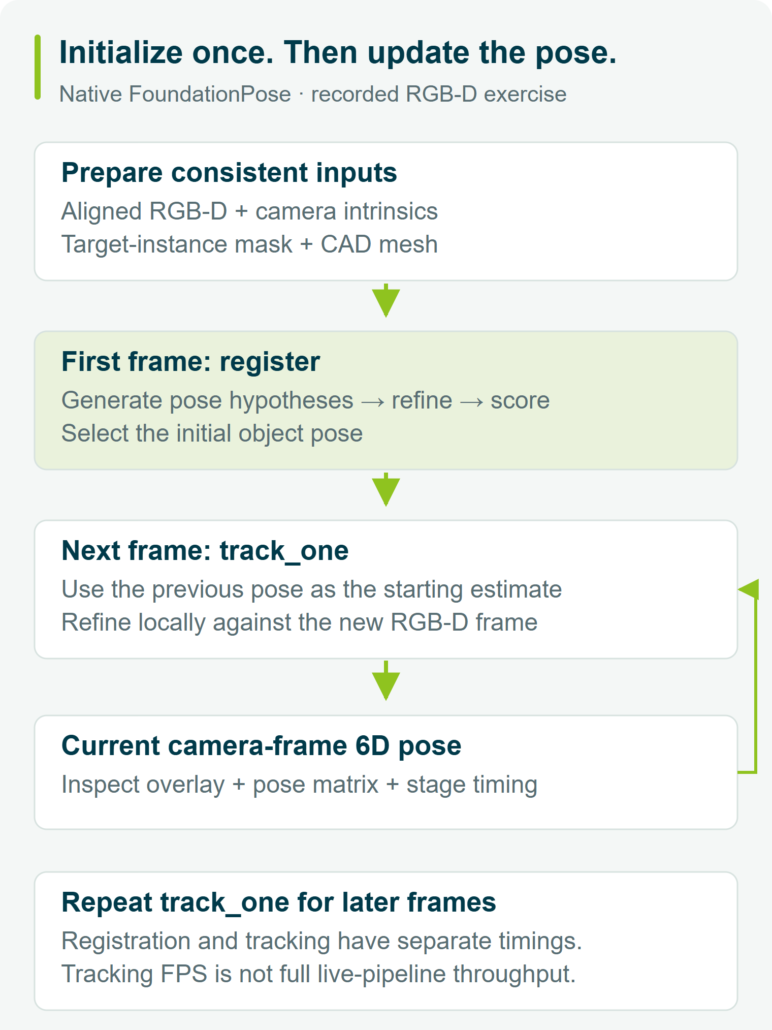
Run the maintained recorded-data entry point from the M04 code directory:
bash scripts/m4/run_m4_5_native_mvp.sh --frames 8
In output/m4/m45_native_mvp/, compare the first and last frame_*_pose.png overlays with the corresponding pose_*.txt matrices and report.json. Check outline alignment, axes and physical scale together.
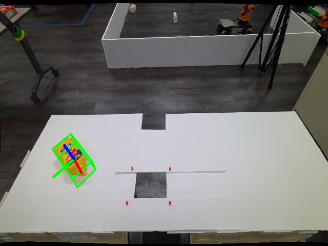
Read the Matrix and the Timing Separately
T_camera_object maps object coordinates into camera coordinates: p_camera = R × p_object + t. A small read-only check helps inspect the exported matrix:
from pathlib import Path
import numpy as np

T = np.loadtxt(Path("output/m4/m45_native_mvp/pose_0000.txt"))
assert T.shape == (4, 4) and np.isfinite(T).all()
R, t = T[:3, :3], T[:3, 3]
print("translation:", t)
print("rotation determinant:", np.linalg.det(R))
print("R.T @ R:\n", R.T @ R)
print("homogeneous row:", T[3])
For a rigid transform, R.T @ R should be near identity, the determinant near +1, and the bottom row [0, 0, 0, 1]. These checks detect structural problems; accuracy still needs calibration or ground truth. If distance is wrong, check depth units, intrinsics and mesh scale. The course CAD example converts millimeter STEP geometry into a meter-scale mesh and records dimensions in object.yaml.
In the report, register_ms describes initialization, track_ms contains update times, and track_fps is derived from tracking-stage latency. The course’s eight-frame Mustard record on J501 / AGX Orin 32GB, JetPack 6.2.1 and CUDA 12.6 reports 11,050.90 ms for registration and approximately 120.43 ms/frame for updates (8.30 FPS). These are existing course measurements; the tracking figure is not the rate of a complete live RGB-D pipeline.
Transform the Pose into the Robot’s Frame
The native bev_pose wrapper uses the prepared mesh with RGB, aligned depth, CameraInfo and an instance mask. It publishes PoseStamped, Detection3DArray and TF; the pose topic is /perception/object_pose. The file-producing MVP does not start this live wrapper.
To express the object pose in the base frame, use the calibrated camera relationship under the column-vector convention:
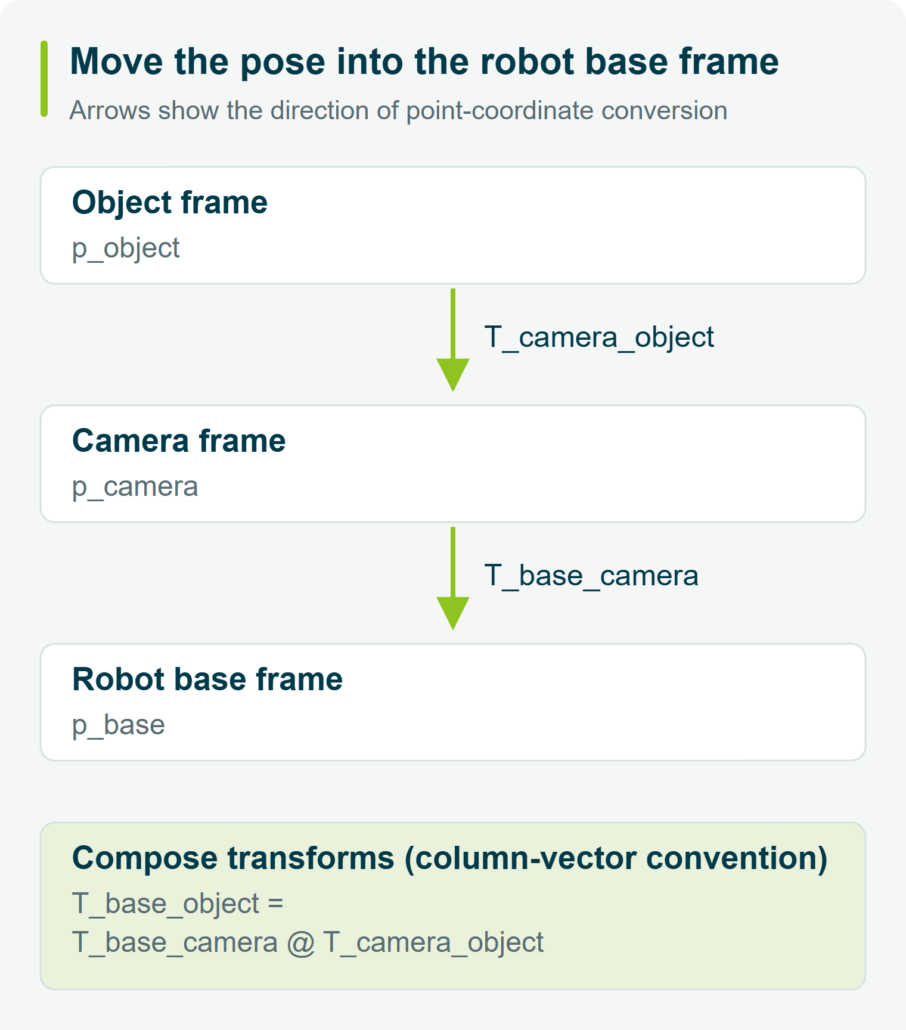
Changing frame_id alone does not transform coordinates. Check direction, units, synchronization and source timestamps; ROS quaternions use x, y, z, w ordering. A valid message and an accurate physical pose require separate verification.
Where Isaac ROS Fits
The Isaac ROS route teaches component graphs, engine profiles and ROS integration around the same pose task. For the course’s TensorRT 10.3 configuration, refine/score use FP32. The 252-candidate and 42-candidate configurations need their matching engines and launch settings; score profile 1/1/252 specifies minimum, optimal and maximum candidate batch sizes.
After preparing the container, engines and recorded assets, the official single-frame entry point is:
M44_MODE=official ./scripts/m4/run_m4_4_isaacros_quickstart.sh
It exposes /output as vision_msgs/msg/Detection3DArray, rather than the native wrapper’s pose topic. The course records valid poses from the Mustard single-frame graph; continuous physical-camera tracking and accuracy acceptance remain further integration work.
Choose the Next Experiment and Find the Course Code
Before moving on, save four results that you can explain:
- One detection frame: pair the source image with its message and check boxes, classes, timestamp and frame.
- One tracking sequence: identify when a detection disappears, an ID changes or a parameter update resets the tracker.
- One region boundary: compare the original image, semantic map and selected mask; distinguish geometry, classification and mapping errors.
- One pose run: connect the inputs, first/last overlays, pose matrices and timing report. State what still needs testing before live robot integration.
Keep the input fixed and change one setting at a time. Those saved results give you a useful baseline for the next experiment—and enough context to discuss a problem with another developer.
Full installation instructions, model assets and advanced configuration are collected here:
| Learning task | Maintained resource |
|---|---|
| Prepare the workspace | Dependencies, build and model preparation |
| Deploy YOLO | Detection, TensorRT and ROS 2 output |
| Investigate track IDs | ByteTrack configuration and experiments |
| Interpret segmentation | SegFormer, masks and evaluation |
| Start with recorded object pose | Native FoundationPose and ROS integration |
| Learn the accelerated component graph | Isaac ROS FoundationPose |
Explore the complete M04 course and code. Star or fork the repository to return to the lessons as your experiments develop. For a question or reproducible problem, check existing course issues and include your versions, input, configuration and relevant output.
The Hardware Behind the Experiments: reComputer Robotics J501
The experiments in this module use reComputer Robotics J501, combining NVIDIA Jetson AGX Orin compute with GMSL camera expansion and robotics interfaces such as USB, Ethernet and CAN. This makes it a practical reference platform for projects that need multi-camera input, local AI inference and ROS 2 communication on an embedded computer.
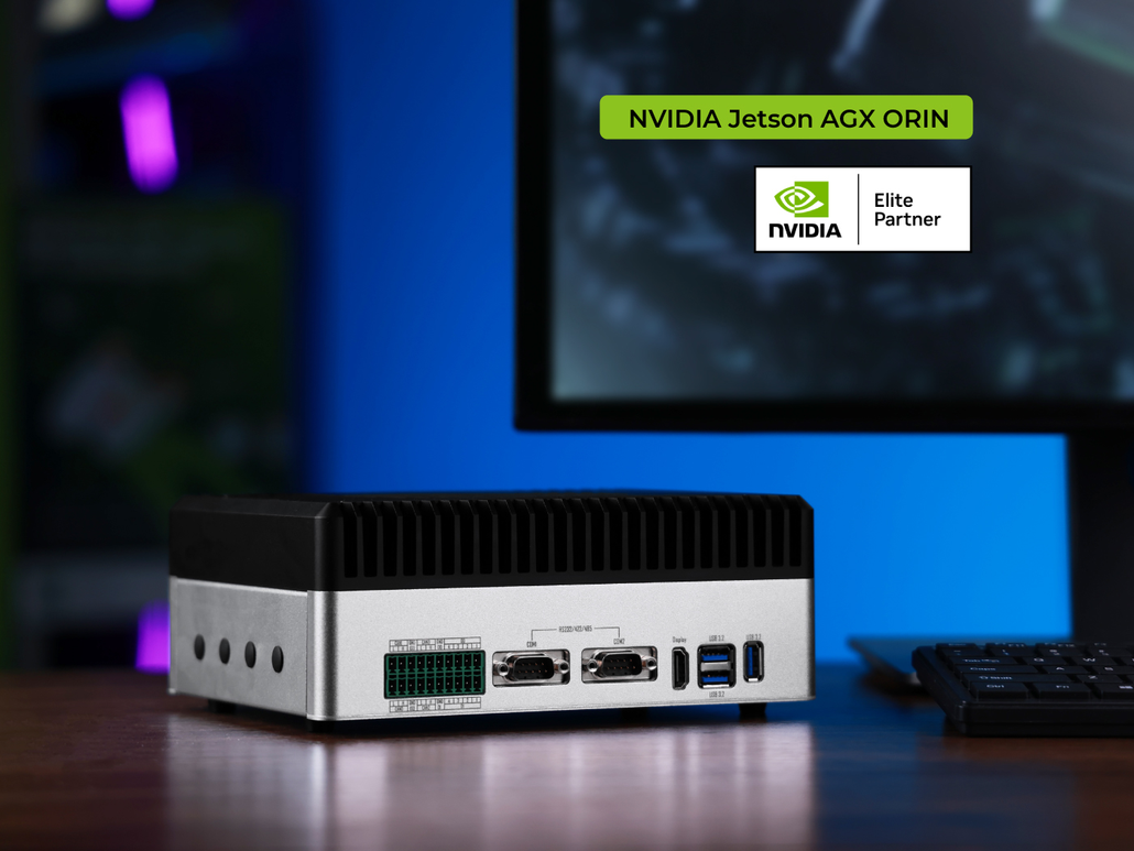
For the matching 32GB configuration, see reComputer Robotics J5011 with GMSL expansion. The J501 Robotics Wiki covers flashing and hardware interfaces. If you are using another J501 configuration, check its module, camera and software requirements against the experiment before reusing the same settings.
The next stage of the course moves into SLAM and 3D reconstruction, building on the perception and sensor data established in the earlier modules. The same engineering habit carries forward: keep the input, coordinate frame, timing and output evidence visible.
Working on a related robot project? Join the Seeed Studio Discord community and Facebook Group to share your detection results, tracking sequences, segmentation masks or pose-estimation experiments. Include the input, configuration and a specific result so other developers can reproduce the issue and contribute useful feedback.
About Author
