Open-Source Modular PCBA Testing: A Complete Guide from Hardware to Test Workflow
Building a functional test setup for one PCBA is relatively straightforward. The challenge is making it reusable across different products.
To reduce repeated hardware and software development, we built a modular testing architecture based on three parts:
Universal Test Box → Product-Specific Adapter Board → Configurable Test Software
Common test resources are integrated into the reusable Test Box, while each new product mainly requires an adapter board and its own test workflow.
This guide explains the complete architecture and walks through a real reference project using the reSpeaker Flex XVF3800 Core Board with XIAO.
Table of Contents
- How the Modular Test System Works
- Why Use a Modular Test Architecture?
- Universal Test Box Capabilities
- Software Test Framework
- How to Adapt the System to Your Own PCBA
Reference Project: reSpeaker Flex XVF3800 Core Board with XIAO
- Test Plan
- Adapter Board Design
- Test Software Configuration
- Test Fixture & Software Reference
- Open-Source Resources
1. How the Modular Test System Works
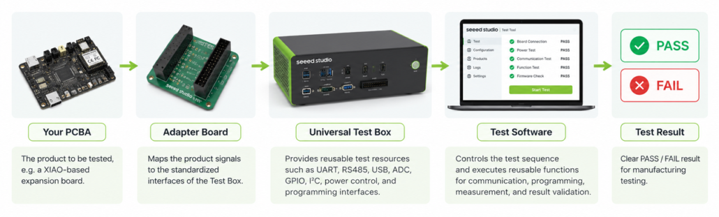
The system separates reusable test resources from product-specific adaptation:
Your PCBA → Adapter Board → Universal Test Box → Test Software → PASS / FAIL
Adapter Board
The Adapter Board provides the product-specific connection between the PCBA and the standardized interfaces of the Test Box.
For a new product, you mainly need to map the required signals to the appropriate Test Box resources.
Universal Test Box
The Universal Test Box integrates common test resources — including UART, RS485, USB, ADC, GPIO, I²C, power control, and programming interfaces — into one reusable platform.
These functions can be reused across different products instead of being redesigned for every new PCBA.
Test Software
The software controls the test sequence and calls reusable functions for communication, programming, measurement, and result validation.
Each product can use its own test configuration, while the underlying software framework remains reusable.
2. Why Use a Modular Test Architecture?
In a traditional product-specific approach, each new product often requires a dedicated companion test board designed around its specific test requirements.
A modular architecture separates reusable testing resources from the product-specific interface, reducing repeated hardware development and making the test system easier to reuse across different products.
| Traditional Product-Specific Test Board | Universal Test Box + Adapter Board | |
| Development | A complete test board must be designed, manufactured, and debugged for each product | Only a relatively simple adapter board needs to be designed |
| Reusability | Test circuits are difficult to reuse across products | The same Test Box can support multiple products |
| Maintenance | Multiple boards and versions need to be maintained | Core test hardware is centralized and standardized |
| Consistency | Different products may use different circuits and layouts | Core test hardware remains consistent |
| Scalability | New test hardware must be developed for each product | The same platform can be reused as more products are added |
| Engineering Effort | Greater dependence on dedicated hardware development | Product adaptation focuses mainly on interface mapping |
The result is more than a different fixture design — it is a reusable platform for functional testing.
3. Universal Test Box Capabilities
The Universal Test Box brings commonly used hardware resources into one reusable platform, allowing different PCBAs to share the same core test hardware.
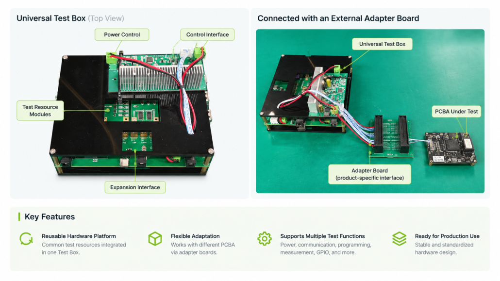
The Test Box exposes standardized Power & ADC, Signal, and Expansion interfaces, allowing product-specific adapter boards to connect only the resources required for each test.
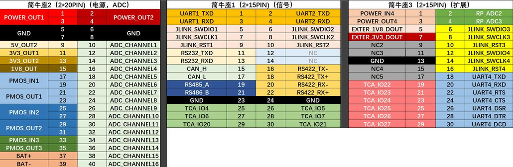
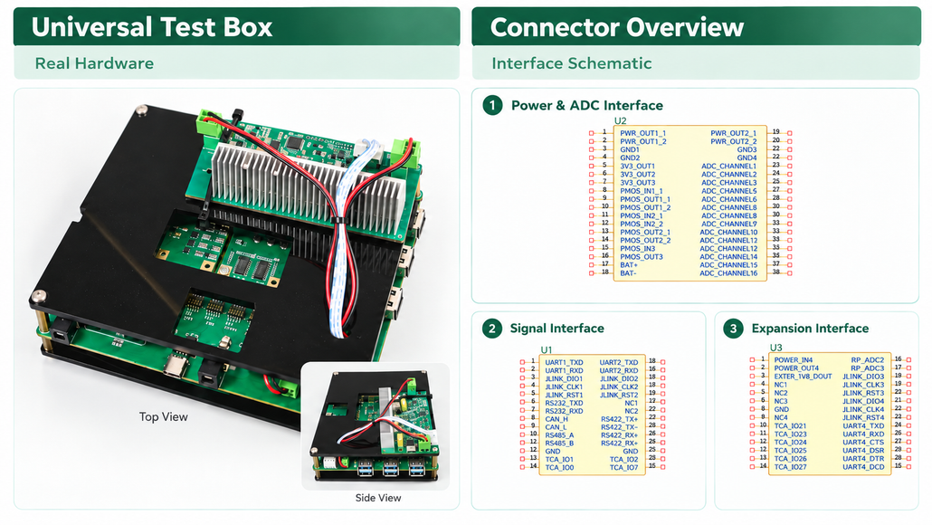
Available Hardware Resources
| Category | Test Resource | Quantity | Notes |
| Measurement | ADC measurement channels | 18 | 2 channels without voltage division; external voltage division is required when the target voltage exceeds 3.3 V |
| Power Control | Controllable power output | 1 | Output voltage equals the Test Box input voltage |
| Controllable DC 5 V output | 1 | — | |
| Controllable DC 3.3 V output | 2 | — | |
| Controllable DC 1.8 V output | 1 | — | |
| PMOS switches | 4 | — | |
| Adjustable simulated battery | 1 | — | |
| Communication | USB-to-UART | 3 | — |
| RS232 | 1 | — | |
| RS485 | 1 | — | |
| RS422 | 1 | — | |
| CAN | 1 | — | |
| USB interfaces | 3 | One USB port supports controllable power output | |
| Programming | J-Link | 4 | — |
| Digital I/O | GPIO | 12 | — |
These resources can be combined according to the test requirements of each product — for example, measuring power rails, verifying communication interfaces, programming firmware, checking GPIO, or testing USB functions.
4. Software Test Framework
The Universal Test Box is paired with a reusable software framework, so each new product does not require a completely new test application.
The framework provides common functions for workflow control, communication, firmware programming, result validation, and test logging. For each product, developers can define the required test sequence through configuration and reuse the existing functions.
Key Software Capabilities
| Category | Capabilities |
| Workflow | Test sequence execution, step control, and PASS / FAIL validation |
| Communication | Serial, SSH, BLE, and other communication functions |
| Programming | J-Link, ESP, XMODEM / YMODEM, and other firmware flashing tools |
| Test Functions | GPIO, RF, audio, and product-specific functional tests |
| Production Support | Barcode handling, product configuration, test logs, and workstation information |
Software Architecture
The framework separates the user interface, workflow engine, reusable test modules, product configurations, firmware, and logs, allowing the same software foundation to be reused across different products.
View Full Software Architecture
Seeed_Factory_Auto_Test_Tool/
├── main.py
├── config.ini
├── function.json
├── product_list.txt
├── environment.yml
├── build.bat
├── scan_hidden_imports.py
├── zip_utf8.py
├── generate_manifest.py
├── app_icon.ico
│
├── window/
│   ├── flash_window.py
│   ├── index_window.py
│   ├── operation_window.py
│   └── view_interface/
│       ├── home_interface.py
│       ├── tool_interface.py
│       ├── config_interface.py
│       ├── add_ini_interface.py
│       ├── add_product_interface.py
│       └── edit_ini_interface.py
│
├── main_function_deal/
│   └── function_thread.py
│
├── custom_component/
│   ├── sys_control/
│   ├── serial_tool/
│   ├── ssh_tool/
│   ├── flash_firmware/
│   ├── esp_tool/
│   ├── other_tool/
│   ├── product_special_func/
│   └── window_component/
│
├── qfluentwidgets/
├── product_function_ini/
├── product_firmware/
├── product_images/
├── product_test_scripts/
├── product_log/
├── temp_log/
├── jlink_tool/
├── esp_tools/
├── adafruit_tools/
├── meshtastic_tools/
└── wt328_wavefile/
5. How to Adapt the System to Your Own PCBA
To adapt the platform to a new PCBA, the process can be divided into four steps:
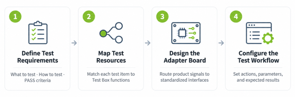
Step 1 — Define Your Test Requirements
Start by identifying what needs to be tested, how it will be tested, and what counts as PASS.
Typical functional tests may cover power rails, voltage levels, GPIO, UART, I²C, USB, buttons, LEDs, sensors, firmware programming, audio, and other product-specific functions.
| Test Item | Method | PASS Criteria |
| 3.3 V rail | ADC measurement | 3.3 V ±5% |
| GPIO | Output toggle / input detection | Expected HIGH / LOW detected |
| I²C | Scan bus | Expected device address detected |
| Firmware | Program device | Programming completes successfully |
| USB | Enumerate device | Device detected by PC |
The test plan becomes the basis for both the hardware connection and the software workflow.
Step 2 — Map Test Requirements to Test Box Resources
Next, match each test item to an available resource in the Universal Test Box.
| Test Requirement | Test Box Resource |
| Voltage measurement | ADC channel |
| GPIO verification | GPIO |
| Serial communication | USB-to-UART |
| Firmware programming | J-Link / supported programming tool |
| USB function | USB interface |
This mapping determines which signals need to be routed through the product-specific Adapter Board.
Step 3 — Design the Adapter Board
The Adapter Board connects the PCBA under test to the standardized interfaces of the Universal Test Box.
Because the common test resources are already integrated into the Test Box, the Adapter Board mainly needs to route the required product signals to the corresponding Test Box resources, rather than rebuilding the complete test circuitry.
We’ll show a complete Adapter Board example in the reference project below.
Step 4 — Configure the Test Workflow
Once the hardware connection is ready, define the test sequence in the software framework.
The workflow can be configured through an INI file, using predefined functions and parameters for each test step. The newer software also supports graphical drag-and-drop configuration to simplify workflow setup.
At its simplest, each step follows the same logic: Action → Expected Result → PASS / FAIL
For example: Enable 3.3 V power → Measure TP7 → 3.3 V ±5% → PASS
The framework remains the same across products; only the test sequence and product-specific configuration need to be adapted.
Reference Project: reSpeaker Flex XVF3800 Core Board with XIAO
To show how the platform works in a real project, we are sharing an open-source test reference based on a Seeed product — the reSpeaker Flex XVF3800 Core Board with XIAO.
The reference covers the complete workflow from test planning and resource mapping to Adapter Board design and software configuration. With multiple power paths, USB, audio, GPIO, I²C, I²S, XIAO, and XMOS firmware, it provides a practical example for adapting the platform to a complex PCBA.
1. Define the Test Items
The original project test plan covers the following areas.
| Test Area | Test Method | PASS Criteria |
| LED | Visual inspection + software confirmation | Green LED turns on at power-up |
| Power inputs | Individually power through USB 5 V, Type-C 5 V, Pad 5 V, XIAO 5 V, and 12 V; ADC measurement at TP3 | TP3: 5 V ±5%; PVCC1: 12 V ±5% |
| VDDIO | ADC at TP7 | 3.3 V ±5% |
| AUDIO_1V8 | ADC at TP6 | 1.8 V ±5% |
| 0V9 | ADC at TP8 | 0.9 V ±5% |
| XMOS firmware & SN | Flash USB test firmware through debug interface and write SN | Firmware flashing and SN writing succeed |
| USB Type-C | Test both connector orientations | XMOS is recognized in both orientations |
| PH connector USB | USB signal verification | PC recognizes XMOS in safe mode |
| XMOS + FPC | Recording with microphone array | Four-channel recording data is normal |
| Codec / Speaker | Audio playback | 10 W / 4 Ω speaker output is normal |
| Mute | Insert/remove headphone during playback and test software mute | Playback switches correctly and software mute works |
| Pin Header GPIO | X0D00 / X0D11 / X0D39 GPIO toggle and input detection | GPIO operates normally |
| I²C | PC controls volume | Volume can be controlled normally |
| I²S | PC recording / playback | Audio data is normal |
| RST | Button test | Pressing Reset resets XMOS |
| Boot | Button + power-on | XMOS enters safe mode |
| XIAO firmware | Program XIAO test firmware / relevant product firmware | Programming completes |
| XIAO D0–D3 | GPIO verification | D1 can reset XMOS; D0/D2/D3 toggle normally |
| XIAO LED | Visual + software confirmation | Red and yellow LEDs turn on as expected |
| XIAO I²C | Scan I²C bus | Codec detected at address 0x18 |
| XIAO I²S | Record through XIAO | Recording data is normal |
| Shipping firmware | Program XIAO shipping firmware | Programming completes |
This test plan becomes the foundation for both the adapter-board design and the software workflow.
2. Adapter Board Design
After the test items and required signals are identified, the next step is to design the product-specific adapter board.
For this reference project, the adapter board only needs to route the required product signals to the standardized Test Box interface rather than recreating all of the test hardware.
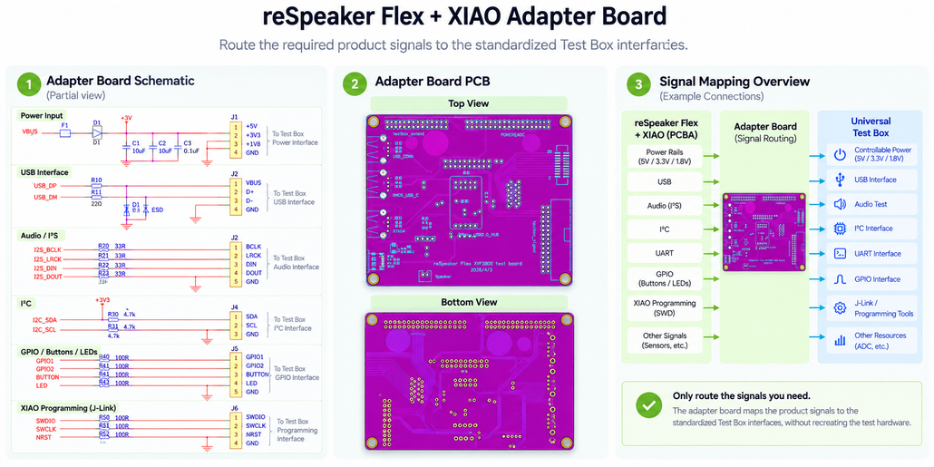
The same principle can be applied to another PCBA:
- Identify required test signals.
- Select the corresponding Test Box resources.
- Map those signals to the standard connector.
- Build the product-specific adapter.
3. Test Software Configuration
After the hardware is connected, the same test framework can be reused for the new product.
For this reference project, the test sequence is defined through an INI configuration. The workflow includes Test Box initialization, board identification, power control, XIAO firmware flashing, device verification, SN checking, and power-off handling.
👇Below is the full configuration example provided for the reference project.
Full Configuration Example
[configure]
barcoder_status=True
upload_file_status=False

[steps]
#begin
start_time=custom_component.product_special_func.operation_prompt_func.time_start

#test box init
test_init_remind=custom_component.other_tool.print_tool.print_message@Step Remind:测试盒初始化....
test_fixture_response=custom_component.serial_tool.serial_funcbox.serial_send_and_receive@2E8A@000A@9600@AT
check_test_fixture_recall=custom_component.other_tool.temp_return_deal.check_string_in_step@test_fixture_response@OK

test_init=custom_component.serial_tool.serial_funcbox.serial_send_and_receive@2E8A@000A@9600@AT+PINOUT=15,17,18,11,12,13|0,0,1,0,0,0
check_test_init=custom_component.other_tool.temp_return_deal.check_string_in_step@test_init@OK

test_gpio_init=custom_component.serial_tool.serial_funcbox.serial_send_and_receive@2E8A@000A@9600@AT+TCA6424AIN=5,6,7,17,18,19,20
check_test_gpio_init=custom_component.other_tool.temp_return_deal.check_string_in_step@test_gpio_init@OK

#scan board qrcode
scan_board_qrcode_remind=custom_component.other_tool.print_tool.print_message@Step Remind:Scan Board SN....
scan_board_qrcode=self.get_barcoder_input
get_product_sn=custom_component.other_tool.temp_return_deal.deal_return_by_length@scan_board_qrcode@18
get_product_sku=custom_component.other_tool.temp_return_deal.deal_return_by_length@get_product_sn@9
check_board_sku=custom_component.other_tool.temp_return_deal.check_string_in_step_multi@get_product_sku@100070894,100026178

#power on product
power_on_product=custom_component.serial_tool.serial_funcbox.serial_send_and_receive@2E8A@000A@9600@AT+PINOUT=15,17,18,11,12,13|0,1,1,0,1,0
check_power_on_product=custom_component.other_tool.temp_return_deal.check_string_in_step@power_on_product@OK

#xiao firm flash and xvf3800 firm version check, then falsh xiao blank
put_on_remind_confirm=custom_component.product_special_func.operation_prompt_func.show_image_selector@产品放上治具压合后, 将治具盒子的产品USB线连接到XIAO的typeC口, 确认产品绿灯亮,XIAO只亮红灯,点击OK@product_images/product_special_images/202004622_respeaker_flex_core/xiao_check.jpg

flash_xiao_test_firm=custom_component.esp_tool.esptool_programer.program_esp_firmware_v49@303A@1001@--chip esp32s3 -b 460800 --before=default_reset --after=hard_reset write_flash --flash_mode dio --flash_freq 80m --flash_size detect 0x0 product_firmware/respeaker_flex_xvf3800/xiao/respeaker_xiao.ino.bootloader.bin 0x8000 product_firmware/respeaker_flex_xvf3800/xiao/respeaker_xiao.ino.partitions.bin 0xe000 product_firmware/respeaker_flex_xvf3800/xiao/boot_app0.bin 0x10000 product_firmware/respeaker_flex_xvf3800/xiao/respeaker_xiao.ino.bin

check_flash_xiao_test_firm=custom_component.other_tool.temp_return_deal.check_string_in_step@flash_xiao_test_firm@True

led_xiao_confirm=custom_component.product_special_func.operation_prompt_func.show_image_selector@确认XIAO的黄灯亮, 点击OK@product_images/product_special_images/202004622_respeaker_flex_core/xiao_led.jpg

xiao=custom_component.serial_tool.serial_funcbox.serial_send_and_receive@303A@1001@115200@XIAO\r\n
check_xiao=custom_component.other_tool.temp_return_deal.check_string_in_step@xiao@OK

xiao_info=custom_component.product_special_func.respeaker_flex_special_func.check_xiao_info@product_function_ini\202004622_xiao_test.ini@get_product_sku
check_xiao_info=custom_component.other_tool.temp_return_deal.check_string_in_step@xiao_info@True

xiao_uart_close_1=custom_component.product_special_func.respeaker_flex_special_func.xiao_serial_close

flash_xiao_blank_remind=custom_component.other_tool.print_tool.print_message@Step Remind: ——————————————  XIAO 出货空白固件烧录 ——————————————

flash_xiao_blank=custom_component.esp_tool.esptool_programer.program_esp_firmware_v49@303A@1001@--chip esp32s3 -b 460800 --before=default_reset --after=hard_reset write_flash --flash_mode dio --flash_freq 80m --flash_size detect 0x0 product_firmware/respeaker_flex_xvf3800/xiao/blank.ino.bootloader.bin 0x8000 product_firmware/respeaker_flex_xvf3800/xiao/blank.ino.partitions.bin 0xe000 product_firmware/respeaker_flex_xvf3800/xiao/boot_app0.bin 0x10000 product_firmware/respeaker_flex_xvf3800/xiao/blank.ino.bin

check_flash_xiao_blank=custom_component.other_tool.temp_return_deal.check_string_in_step@flash_xiao_blank@True

#check product sn
read_sn_remind=custom_component.other_tool.print_tool.print_message@Step Remind: —————————————— SN检查 ——————————————
read_sn=custom_component.product_special_func.respeaker_flex_special_func.read_xmos@0x000003f8@--id 0
test_read_sn=custom_component.other_tool.temp_return_deal.step_two_return_equal@read_sn@get_product_sn
check_test_read_sn=custom_component.other_tool.temp_return_deal.check_string_in_step@test_read_sn@True

#power off
power_off_sn=custom_component.serial_tool.serial_funcbox.serial_send_and_receive@2E8A@000A@9600@AT+PINOUT=15,17,18,11,12,13|0,0,1,0,0,0
check_power_off_sn=custom_component.other_tool.temp_return_deal.check_string_in_step@power_off_sn@OK
power_off_sn_delay=time.sleep@1

#end step
end_steps=custom_component.other_tool.print_tool.print_message@writeSN END!
end_time=custom_component.product_special_func.operation_prompt_func.time_end
The important point here is not that every project uses the same configuration.
Instead, the framework remains reusable while the configuration changes according to the product.
4. Test Fixture and Software Reference
Test Fixture
The reference project uses a physical fixture to position the PCBA and make repeatable connections to the required test points and interfaces.
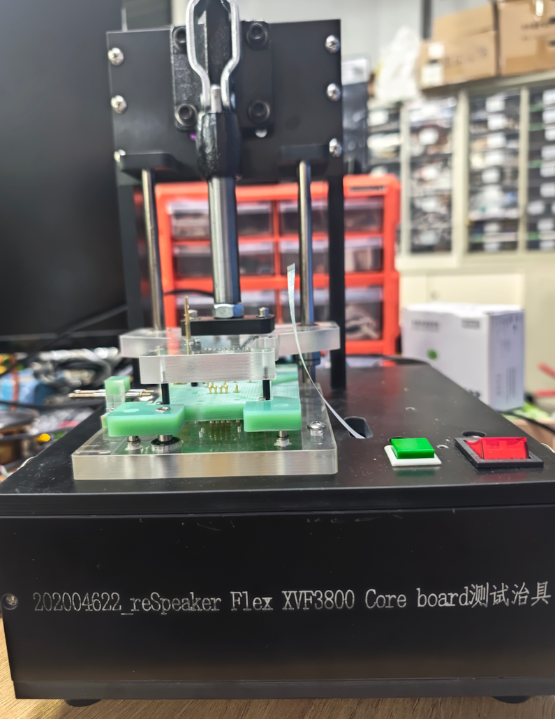
The mechanical fixture, product adapter, and Universal Test Box work together to turn the test plan into a repeatable manufacturing process.
Reference Test Software
In our production environment, Seeed uses an internal test application to execute configured test sequences, display test progress, and determine PASS / FAIL results.
Together with the Test Box hardware, it demonstrates how a complete functional test system can be built around a reusable hardware and software architecture.
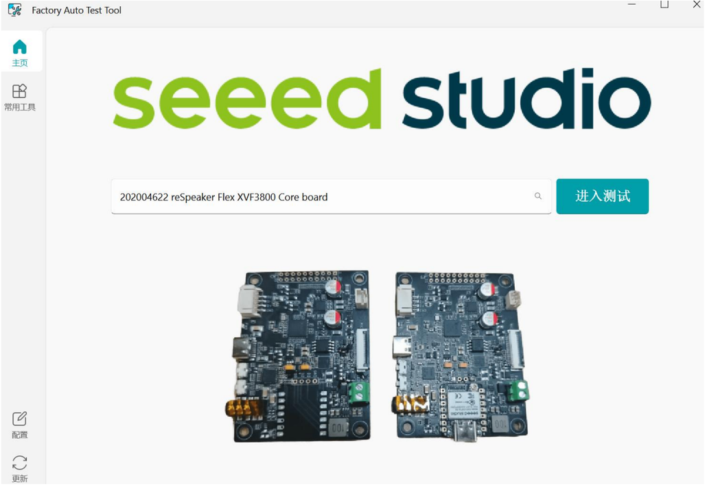
Developers can use the same architecture and interface concepts to build their own test system. If you are interested in building a similar test setup for your own product, contact Seeed Fusion to discuss a customized solution.
A typical test application may include:
- hardware resource control;
- test-sequence execution;
- data collection and validation;
- product-specific PASS / FAIL criteria;
- test-result display and logging.
Ready to Build Your Own Test Workflow?
Use the open-source reference to adapt the architecture to your own XIAO-based expansion board or custom PCBA.
Have questions or need help with your test setup? Contact us at [email protected]
About Author
