Why Do So Many Robot Arms Have Six Axes? Understanding 6-DOF Robotics
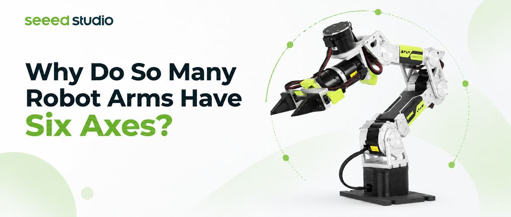
Six-axis robot arms are common in industrial automation, research laboratories, and increasingly in open-source robotics projects. Whether a robot is assembling components, handling objects, or learning a manipulation task, six axes are often part of its mechanical design. Yet the reason for this configuration is not immediately obvious. If a robot operates in three-dimensional space, where an object’s position can be described using X, Y, and Z coordinates, why does it need six axes rather than three?
The answer becomes clearer when we consider what happens after a robotic arm reaches its target. A gripper can arrive at the correct location and still fail to pick up an object because it approaches from the wrong direction. Successful manipulation requires the robot to control not only where its tool is positioned, but also how that tool is oriented. This distinction provides the foundation for understanding six degrees of freedom, how articulated robot arms coordinate their joints, and why robot kinematics remains essential as AI models become increasingly involved in robotic decision-making.
Why Reaching an Object Is Only Half the Task
Imagine using a robotic arm to pick up a cup from a table. A camera detects the cup, and the controller moves the gripper toward its estimated position. The arm reaches the target coordinates, but the fingers approach at an unsuitable angle and cannot close around the object. From a positioning perspective, the movement may have been successful; from a manipulation perspective, the task has failed.
The same challenge appears in more demanding applications. A connector must approach its socket with the correct alignment, a tool must contact a surface at an appropriate angle, and a gripper needs to account for an object’s orientation before attempting to grasp it. Knowing where an object is located does not fully describe how a robot should interact with it. The end effector must reach a suitable position and orientation together.
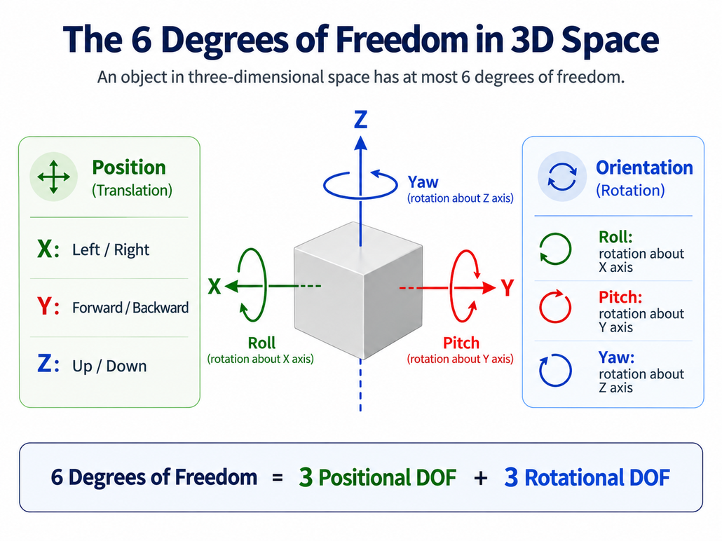
Robotics describes this combination using the concept of a pose. Position specifies an object’s location along three spatial directions, conventionally represented by X, Y, and Z. Orientation describes its rotational relationship to a reference frame and has three independent degrees of freedom, commonly represented using Roll, Pitch, and Yaw angles.
Together, these form 6-DOF (Six Degrees of Freedom).
What makes a robotic arm 6-DOF?
A complete end-effector pose in three-dimensional space has six degrees of freedom:
- 3 translational DOF: X, Y, and Z describe position.
- 3 rotational DOF: Roll, Pitch, and Yaw describe orientation.
A conventional six-axis articulated robot uses coordinated rotary joints to provide the motion capability needed for complete end-effector pose control within its usable workspace.
This explains why six-axis robotic arms are widely used for general-purpose manipulation. They provide the independent motion needed for a tool to approach objects from different positions and orientations instead of relying on a fixed approach direction.
Having six axes does not, however, guarantee that every possible pose is reachable. Link geometry, joint limits, workspace boundaries, and singular configurations still constrain the robot’s movements. Six degrees of freedom provide the basis for complete pose control, while the mechanical structure determines where and how that capability can be used.
How Six Rotary Joints Produce Coordinated Motion
A common misconception is that a six-axis robot contains one motor dedicated to X, another to Y, and a third to Z, with three additional motors handling orientation. That arrangement is possible in certain mechanical systems, but conventional articulated robot arms generally work differently.
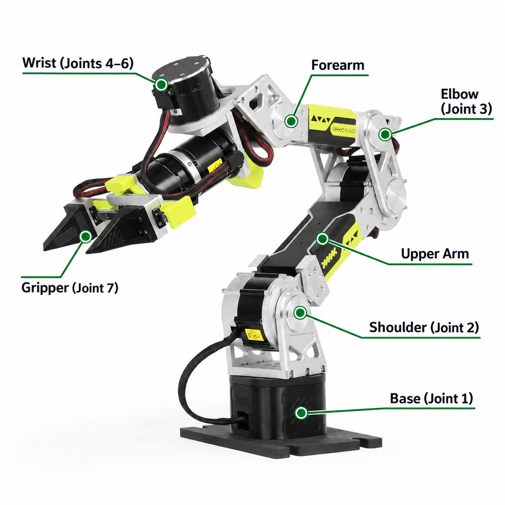
An articulated robot arm consists of rotary joints connected through a mechanical chain. Each joint rotates around its own axis, and its movement changes the position and orientation of the links that follow it. The final pose of the end effector is therefore determined by the combined configuration of the entire arm rather than by any single joint.
Consider commanding a gripper to move forward by ten centimeters while maintaining the same orientation. Although the tool follows a simple path, several joints may need to rotate simultaneously. The shoulder and elbow can change the arm’s reach, while the wrist adjusts to compensate for changes in orientation. What appears to be a straightforward linear movement at the end effector is the result of coordinated motion across multiple joints.
This relationship is particularly useful to observe on real six-axis robotic arms such as Seeed Studio’s reBot and SO-ARM. Moving one joint independently rarely produces a simple Cartesian translation of the gripper. Once several joints move together, however, the arm can perform more intuitive movements, including approaching an object along a chosen direction while maintaining the appropriate tool orientation.
Robot controllers describe these movements through two related representations. Joint space expresses the robot’s configuration through individual joint positions, while Cartesian space describes the end effector’s position and orientation relative to a reference frame. Developers often define manipulation tasks in Cartesian space because those targets correspond to physical actions. The robot’s actuators, meanwhile, execute commands that change its joint configuration.
Translating between these representations is one of the central responsibilities of robot kinematics. The relationship is fundamental to conventional robot programming and equally relevant to modern systems in which motion targets are generated from camera observations or learned policies.
Forward and Inverse Kinematics in Practice
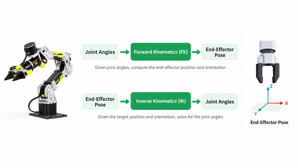
Two fundamental concepts describe the relationship between a robot’s joints and its end effector: Forward Kinematics (FK) and Inverse Kinematics (IK).
Forward kinematics determines the end-effector pose from known joint positions. Given the robot’s link geometry and current joint angles, its kinematic model calculates where the tool is located and how it is oriented. This calculation is useful for monitoring the robot’s configuration, simulating movements, and understanding how individual joint changes affect the end effector.
Inverse kinematics approaches the problem from the opposite direction. A developer specifies a desired end-effector pose, and the system determines which joint configurations could achieve that target. In a vision-guided manipulation task, for example, a perception system may estimate a suitable grasp pose beside an object. Before the robot can execute the grasp, it must determine how its joints should move to reach that pose.
The inverse problem can be more complicated because the relationship is not always one-to-one. Depending on the robot’s geometry, several joint configurations may produce the same end-effector pose. Some configurations may approach joint limits or create collision risks, while others may require less movement from the robot’s current position. Certain target poses may have no feasible solution at all.
This is where kinematics becomes more than a mathematical exercise. A robot may know where its tool should go but still need to determine whether that pose is reachable and which configuration is appropriate. Motion planning must then consider how to move between configurations while respecting physical constraints. For developers troubleshooting an unsuccessful movement, distinguishing between an incorrect target pose, an infeasible IK solution, and a problematic trajectory can save considerable time.
The relationship can be summarized as follows:
| Forward Kinematics (FK) | Inverse Kinematics (IK) | |
|---|---|---|
| Input | Joint positions | Target end-effector pose |
| Output | End-effector pose | Possible joint configurations |
| Main question | Where is the tool? | How can the robot reach the target? |
| Typical use | State calculation and simulation | Target reaching and manipulation |
These calculations are largely hidden when a robotic arm performs a smooth movement. In a simulation or robot-control interface, a developer may simply move a target pose and watch the robot adjust. Behind that interaction, the system is managing the relationship between the desired tool pose and the joint configurations that can achieve it.
Why Five, Six, and Seven Axes Serve Different Purposes
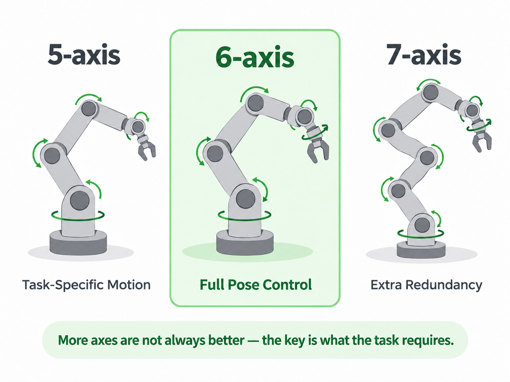
Six-axis designs are common, but they are not inherently better for every application. The appropriate number of axes depends on the movements a robot needs to perform, the environment in which it operates, and the complexity the task justifies.
Many industrial applications take place in constrained workspaces. A robot repeatedly transferring components between known positions may have little need to vary its tool orientation beyond a limited range. In these circumstances, a mechanism with fewer degrees of freedom can perform the task effectively without the additional joints required for general-purpose pose control. SCARA robots illustrate this approach, as their geometry is particularly useful for certain planar assembly and handling operations.
Five-axis systems can likewise be appropriate when a task imposes constraints on the end-effector orientation. Rather than viewing these designs as incomplete six-axis robots, it is more useful to consider which movements the application actually requires. Additional freedom has value when it supports a meaningful operational need.
Seven-axis articulated arms address a different objective by introducing kinematic redundancy. A complete spatial pose still has six degrees of freedom, but an additional controllable joint gives the robot more options for arranging its internal configuration while maintaining the same end-effector pose.
The human arm provides an intuitive example. You can hold your hand in approximately the same location and orientation while moving your elbow to a different position. A redundant robotic arm can exploit similar flexibility to adjust its posture, move away from joint limits, or find a configuration better suited to nearby obstacles. Whether these advantages can be realized depends on the robot’s mechanical design and control algorithms.
Redundancy also introduces additional mechanical and computational complexity. For tasks that do not benefit from extra posture choices, six axes may provide a more practical balance between flexibility and system complexity.
The differences can be summarized without treating any configuration as universally superior:
- 5-axis: Suitable for tasks with more constrained motion requirements.
- 6-axis: Supports complete end-effector pose control within the robot’s usable workspace.
- 7-axis: Adds redundancy for additional internal posture choices.
The engineering question is not how many axes a robot can have, but how many it needs to perform its intended work effectively.
Why Six Degrees of Freedom Still Matter in Physical AI
The growing interest in Physical AI, Embodied AI, LeRobot, imitation learning, and Vision-Language-Action (VLA) models is changing how developers build robotic systems. Instead of defining every movement through a fixed sequence of commands, developers can collect demonstrations, train policies, and experiment with models that generate actions from visual observations and task instructions.
These approaches change how actions are selected, but they do not remove the physical constraints of manipulation. A learned policy may identify a useful grasping action, yet the robot still needs to execute that action through real joints and motors. The target may be outside the arm’s workspace, the requested orientation may be difficult to achieve, or the planned movement may intersect an obstacle.
Consider a vision-based manipulation system attempting to grasp an object near the edge of a worktable. The perception system identifies the object, and an AI policy predicts a suitable grasp target. If that target is expressed as an end-effector pose, the robot must determine whether it is reachable and how to approach it without colliding with the table. If the selected approach is infeasible, the system may need to choose another grasp candidate or revise its action. In a learning-based system that outputs joint commands directly, the controller must still enforce the relevant physical and operational constraints.
This illustrates how robot learning and classical robotics work together. AI models can help select actions based on changing observations, while the robot’s control architecture must translate those actions into executable movements. Depending on the system, a learned policy may communicate with the robot through joint positions, end-effector targets, or other action representations.
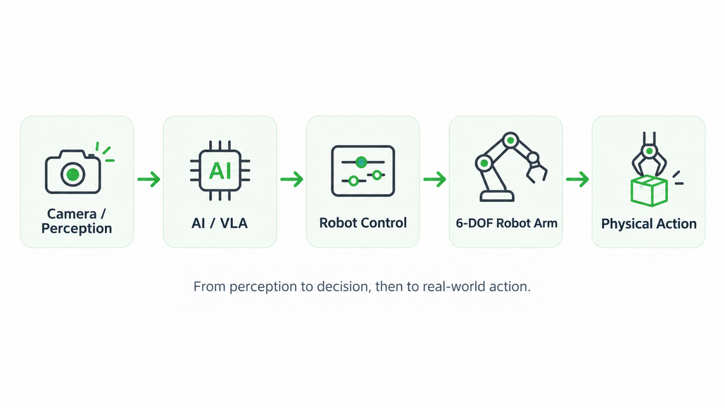
A typical perception-to-action workflow includes:
Perception → AI Decision-Making → Robot Control → Joint Motion → Physical Interaction
Understanding degrees of freedom and kinematics makes these interfaces easier to reason about. It helps developers understand why a model-generated action may fail on real hardware, how to diagnose reachability problems, and where conventional planning or control methods fit into a learning-based workflow.
For Physical AI, the challenge is not simply to generate an action that appears reasonable in software. It is to make perception, decision-making, and physical execution work together reliably in an environment that may change between observation and movement.
Putting 6-DOF Robotics into Practice with reBot and SO-ARM
The relationship between joint motion and end-effector pose becomes more intuitive when developers can experiment with real hardware. Observing how individual joints change the tool’s position, testing Cartesian targets, and understanding what happens near workspace limits provide practical experience that diagrams alone cannot replace.
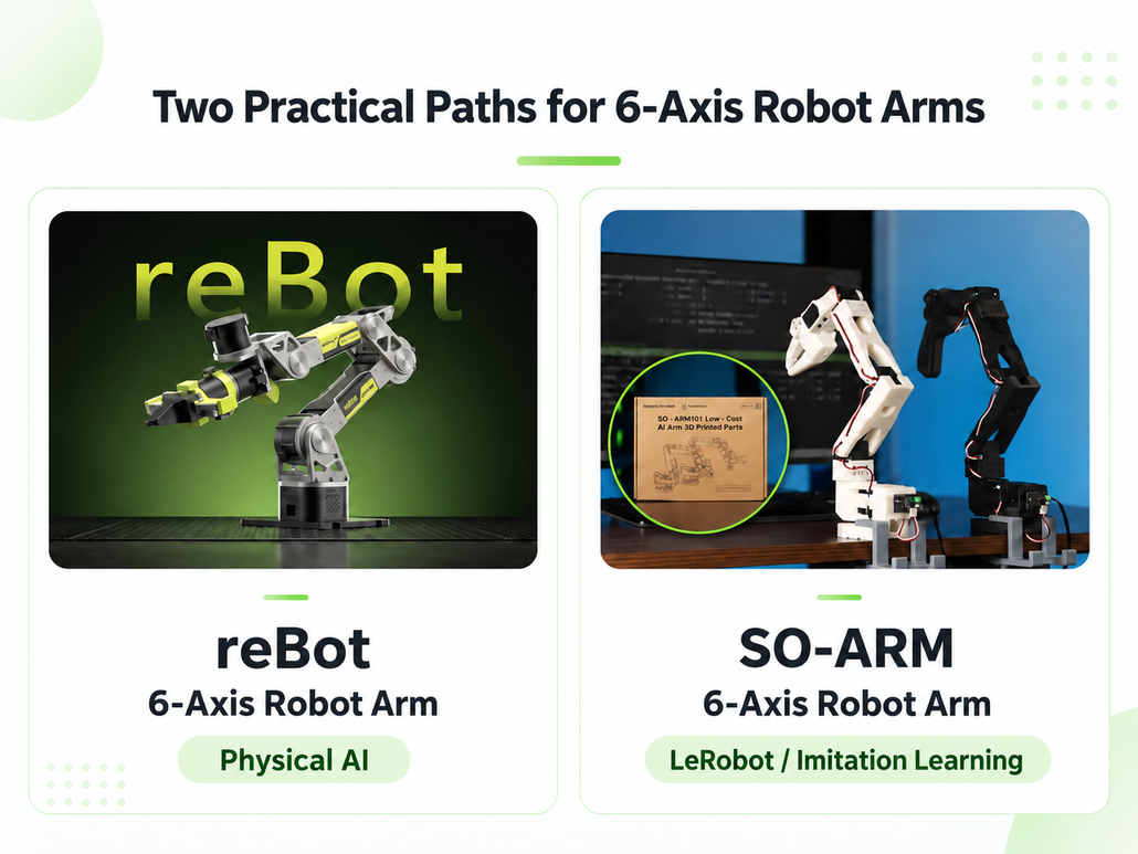
Seeed Studio’s reBot and SO-ARM provide two development paths for exploring six-axis manipulation. Both connect foundational robotics concepts with real robot behavior, while their documentation and learning resources support different areas of experimentation.
reBot: Exploring Articulated Robot Control and Physical AI
For developers interested in articulated robot motion, manipulation, and broader Physical AI development, reBot Arm B601 provides a platform for hands-on experimentation. Its B601-DM and B601-RS configurations offer options for robotic arm development, supported by getting-started documentation and additional learning resources.
A useful exercise is to compare joint-space and Cartesian-space movements. Starting from a known robot configuration, a developer can observe how individual joint rotations affect the end-effector pose, then explore how coordinated joint motion produces a desired tool movement. This creates a practical connection between the arm’s mechanical structure and the kinematics used to describe its motion.
Developers can explore the available configurations through reBot Arm B601-DM and reBot Arm B601-RS Assembled Kit with Gripper. For those deciding between configurations, Seeed Studio also provides a guide comparing reBot B601-RS and B601-DM.
SO-ARM: Exploring LeRobot and Imitation Learning
Developers more interested in teleoperation, demonstration collection, and imitation learning can explore these workflows through SO-ARM101 and its associated LeRobot resources.
In a typical imitation-learning workflow, a developer demonstrates a manipulation task while recording observations and robot actions. Those demonstrations become training data for a policy that attempts to reproduce the behavior. Evaluating the resulting policy introduces practical questions about action representations, consistency of demonstrations, and the difference between successfully reproducing a movement and reliably completing a task.
The mechanical principles discussed earlier remain relevant throughout this process. Whether the robot follows teleoperation commands or actions generated by a trained policy, its joints must coordinate to produce the intended physical behavior. Understanding pose, joint configurations, and workspace constraints helps developers interpret what happens when a learned action succeeds or fails.
Developers can begin with the SO-101 Assembled Kit Pro and the SO-ARM / LeRobot Getting Started guide. For further inspiration, Seeed Studio has collected SO-ARM101 projects ranging from grasping to imitation learning.
These platforms represent different starting points rather than mutually exclusive approaches. One developer may begin with articulated robot control and coordinated joint movement, while another focuses on collecting demonstrations and experimenting with learning-based manipulation. Both approaches depend on understanding how software-defined actions relate to the physical capabilities of a robotic arm.
Where Should You Start?
The right starting point depends on what you want to build. Developers interested in understanding the mechanics of robotic arm movement may prefer to begin with joint control, while those exploring robot learning may begin with teleoperation and demonstration data.
| Development goal | Suggested starting point | Resource |
|---|---|---|
| Explore articulated robot control and manipulation | reBot B601 | reBot B601-RS |
| Experiment with LeRobot and imitation learning | SO-ARM101 | SO-101 Assembled Kit Pro |
| Follow a robot-learning setup tutorial | SO-ARM + LeRobot | Getting Started Guide |
| Explore the broader Physical AI ecosystem | Seeed AI Robotics | AI Robotics Resources |
Frequently Asked Questions About 6-Axis Robot Arms
What is a 6-axis robot arm?
A 6-axis robot arm is a robotic manipulator with six controllable joint axes. In a conventional articulated configuration, these joints provide the motion capability needed to control the end effector’s position and orientation within the robot’s usable workspace, subject to mechanical and kinematic constraints.
Is a 6-axis robot arm the same as a 6-DOF robotic arm?
The terms are closely related but describe different concepts. Six-axis refers to the number of controllable joint axes, while 6-DOF describes six independent degrees of freedom. A conventional six-axis articulated robot generally provides six-degree-of-freedom end-effector motion away from singular configurations.
What is the difference between a 6-axis and a 7-axis robot arm?
A six-axis articulated arm typically provides the motion capability required for complete end-effector pose control. A seven-axis arm adds kinematic redundancy, allowing additional joint configurations for the same end-effector pose. This flexibility can support posture adjustment and obstacle avoidance when enabled by the robot’s design and control system.
Why are forward and inverse kinematics important?
Forward kinematics calculates the end-effector pose from known joint positions, while inverse kinematics identifies joint configurations that could achieve a desired pose. These calculations connect task-space goals with physical joint movements and are fundamental to robotic arm control.
Can a 6-axis robot arm be used with LeRobot and Physical AI?
Yes. Six-axis robotic arms can serve as manipulation hardware for teleoperation, imitation learning, visual perception, and Physical AI applications. Supported workflows and software integrations depend on the robot platform. Seeed Studio’s reBot and SO-ARM ecosystems offer different resources for exploring these applications.
Continue Exploring Robotics with Seeed Studio
Understanding why six-axis robotic arms are common provides a useful foundation for robotics development, but their value becomes clearer through experimentation. Moving individual joints, adjusting target poses, and investigating unsuccessful grasps reveal how closely mechanical design, robot control, and task execution are connected.
Developers interested in articulated robot control and broader Physical AI applications can explore reBot Arm B601. Those interested in teleoperation and imitation learning can begin with SO-ARM101 and its LeRobot learning resources. Additional development platforms and tutorials are available through the Seeed Studio AI Robotics ecosystem and the LeRobot and Embodied AI resource hub.
Six-axis robotic arms remain relevant because they provide a practical foundation for controlling both position and orientation in three-dimensional manipulation. The same principles that govern a conventional pick-and-place movement also help explain how robots execute actions generated by modern learning-based systems. For developers building toward Physical AI, understanding that relationship is an important step toward creating robots that can interact more reliably with the physical world.
Join the Seeed Studio Robotics Community
Building a robot arm is only the beginning. Whether you’re experimenting with 6-DOF motion control, exploring LeRobot and imitation learning, or integrating VLA models into your Physical AI projects, there’s always something new to learn from other developers.
At Seeed Studio, we believe some of the most valuable robotics insights come from sharing real projects, discussing technical challenges, and learning from what works—and what doesn’t. We’d love to see what you’re building, whether it’s your first successful grasp, a teleoperation experiment, or a more advanced robotic manipulation system.
Connect with fellow makers, researchers, and robotics developers through our communities:
- Discord — Seeed Robotics Community: Discuss technical challenges, exchange development ideas, and get feedback on your projects.
- WhatsApp — Robotics Builders Group: Connect with other builders, share progress, and join ongoing robotics discussions.
- Facebook — Seeed Studio AI Robotics Community: Showcase your demos, discover community projects, and share your robotics development journey.
Whether you’re working with reBot, SO-ARM, LeRobot, or your own custom robotic arm, you’re welcome to join the conversation. Share your latest build, ask a question, or show the community how you’re bringing Physical AI into the real world.
Let’s keep building, experimenting, and learning together.
About Author
