Work from Home: What Do You Need for An Electrical Engineer’s Home Lab

In order to prevent the spread of COVID-19, the coronavirus, more and more people are being asked to work from home. We prepared this guide introduced how to set up an electronics home lab. We hope this guide will help you find the right tools and equipment for your home workspace and finish your projects at home.
We also create the topic of “Work from Home” by keeping updating electronics tech tips.
Apply the coupon code [TOOLS20] to enjoy 20% OFF for the products listed on the page of Work from Home. Hope the following guides and products recommendation will help you to build the workspace for your projects need. Today, we will be covering these various tools and related tech tips:
- Oscilloscopes
- Programmers
- In-Circuit Programmer
- AVR Programmer
- Converters
- USB to UART Converter
- DC Power Converter
- Analyzers
- Logic Analyzers
- CAN Analyzers
- USB Cable and Charger Tester
- Spectrum Analyzers
- Antenna Analyzers
- SPI Driver Adapter
- Power Supply
- Signal Generators
- Current and Voltage Detector
- Hand Tools
- Soldering Tools
Oscilloscopes
An oscilloscope is a type of electronic test instrument that can graphically display signal voltage changes. Other signals (such as sound or vibration) can be converted to voltages and displayed on the screen of the oscilloscope.
Engineers use oscilloscopes to study the changing process of various electrical phenomena for laboratory work.
Digital storage oscilloscopes (DSO) are powerful instruments used to display and measure electronic signals that change over time DSO can help to determine which device is operating normally and which one is failing. Oscilloscopes can also help engineers determine if a newly designed device will perform the way they want.
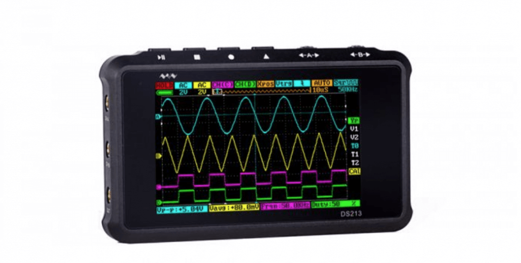
We recommend MiniDSO DS213 Nano 4 Channel 100MSa/s.
The DS213 is a 5-track 4-wire universal electronic engineering task digital storage oscilloscope based on the ARM Cortex M3 core. Using the FPGA’s external ADC’s management control and data cache mode of operation, it provides four application partitions for loading and upgrading up to four different application firmware. With a built-in 8MB USB stick, users can store waveforms and upgrade the system firmware.
DSCope U3P100 Dual-Channel 1GSa/s Sampling/100Mhz Bandwidth USB3.0 – Portable Oscilloscope
DSCope U3P100 oscilloscope is an ultra-portable, dual-channel, USB-based digital oscilloscope, with 100MHz bandwidth, 1GSa/s sample rate, 2M real-time and 256M single record length.
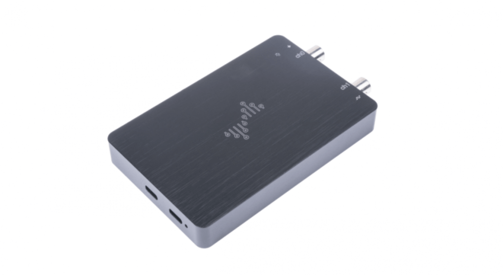
Pocket Science Lab Development Board from pslab.io is a small USB powered hardware extension for your Android phone or PC that lets you measure all kinds of things.
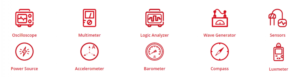
Pocket Science Lab Dev Board comes with a built-in Oscilloscope, it only costs $64.90 but ingrates with multiple powerful functions: Oscilloscope, Multimeter, Logic Analyzer, Wave Generator, Power Source, Accelerometer, Barometer, Compass, Sensors, Luxmeter and many more without the need of programming!
Programmers
AVR Programmer
The programmer is designed for use with AVR microcontrollers, also making it compatible with standard AVR programming software. The in-system programmers usually are used to program AVR microcontrollers and AVR-based controller boards such as Arduino Uno and Seeeduino 4.2.
The programmer provides an interface to transfer a compiled AVR program from your computer to the target AVR’s non-volatile memory, allowing the microcontroller protocol can “understand” and run the program.
AVR is a family of microcontrollers made by Atmel, which usually stands for 8-bit and 32-bit microcontrollers. When you create a program into an AVR, the most common way is through In-Circuit Serial Programming. The output of the compilation must be a file that the microcontroller can “understand” – which called AVR programming.
MPLAB PICkit 4 In-Circuit Debugger/Programmer
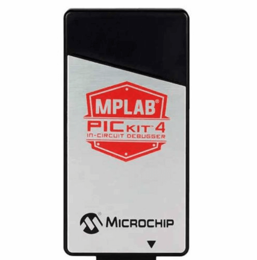
The MPLAB® PICkit™ 4 is a fast debugger for board programming. It’s more user-friendly than its predecessor PICkit3 with a wider target voltage and an additional micro SD card slot.
ISP programmers have many advantages in size, port availability, and power source. Microchip provides a detailed ICSP programming guide
ST programmer
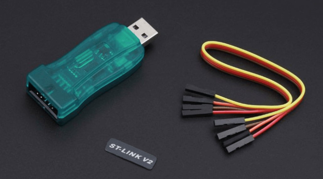
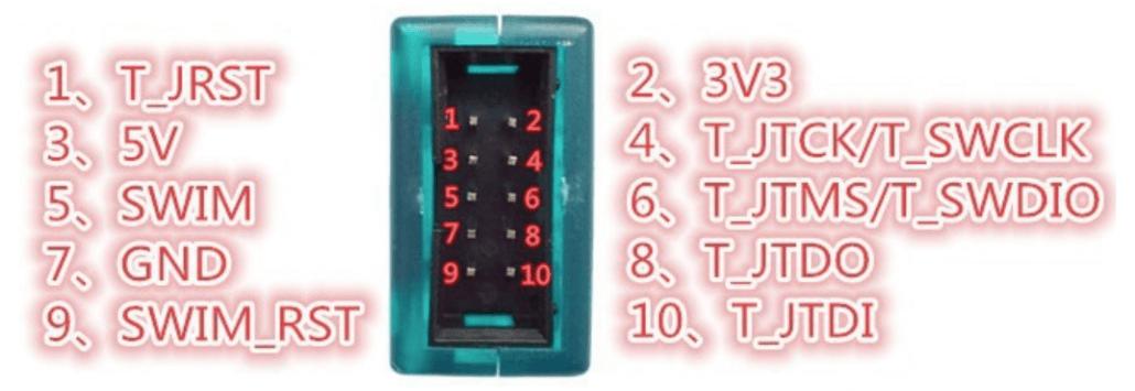
STMicroelectronics provides a range of programming tools for developers able to program the microcontroller via various protocols such as STLink, USB DFU, UART, or SPI.
The ST-LINK/V2 is an in-circuit debugger and programmer for the STM8 and STM32 microcontroller families
JTAG
JTAG stands for Joint Test Action Group. When designing a printed circuit board, it is currently mainly used to test the sub-blocks of integrated circuits, and also provides a debugging mechanism useful in embedded systems.
With the help of debugging tools, such as in-circuit simulators, JTAG is used as a mechanism for signal transmission, allowing programmers to read the debugging module integrated on the CPU via JTAG. The debug module allows programmers to debug software in embedded systems.
Sipeed USB-JTAG/TTL RISC-V Debugger
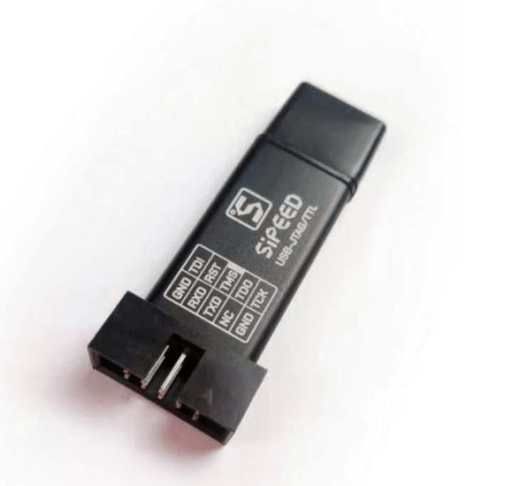
Support the full range of STM32 SWD debugging interface, a simple 4-wire interface (including power), fast, stable; interface definition housing directly marked! No need to read the manual
Support the full range of STM8 SWIM download debugging (common development environments such as IAR, STVD etc. are supported); supported software versions as follows:
– ST-LINK Utility 2.0 and 4.2.1 above
– STVD and above
– STVP 3.2.3 and above
– IAR EWARM V6.20 and above
– IAR EWSTM8 V1.30 and above
– KEIL RVMDK V4.21 and above
Converters
USB to UART Converter
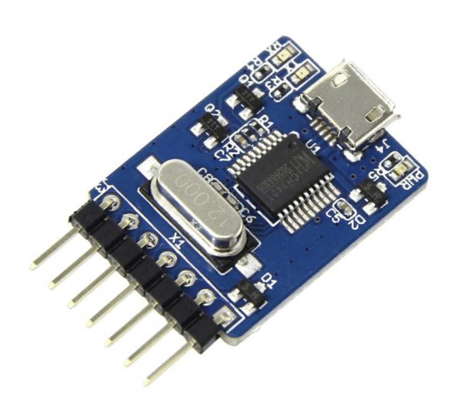
USB To Uart 5V is a USB to serial adapter, which is base on CH340, CH340 is a USB bus convert chip and it can realize USB convert to serial interface, USB convert to IrDA infrared or USB convert to printer interface
DC Power Converter
Adjustable DC&DC Power Converter (1V – 12V&1.5A)
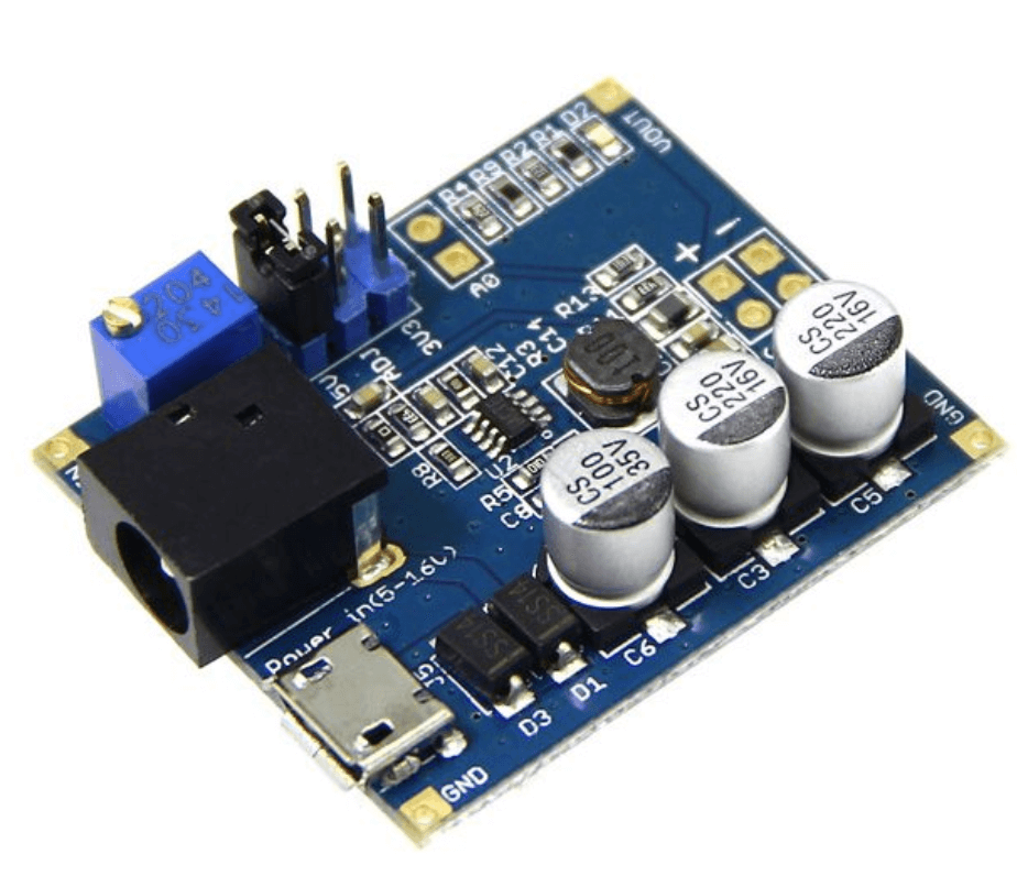
This is a DC/DC step-down voltage regulator that converts input voltage between 4.5V and 16V into a smaller voltage between 1V and 12V, capable of driving a 1.5A load with excellent line and load regulation. You might need different voltages (1-12V) for your devices and different projects. This module can accelerate prototyping because you can get easily the voltage you need (such as 1.2V,1.8V,3.3V, 5V and 9V).
Analyzers
Logic Analyzers
A logic analyzer is an electronic instrument that can collect and display digital circuit signals. The logic analyzer has a very high sampling rate, can accurately capture and display multiple digital signals and provides a complete test and measurement method to quickly find signal timing problems.
Logic analyzers are very effective for testing and analyzing complex digital systems. The logic analyzer uses the clock to collect and display digital signals from the test equipment for timing determination.
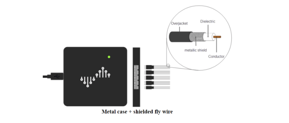
DSLogic U3Pro16 1Ghz Sampling 16 Channel USB3.0 – Portable Logic Analyzer
DSLogic Logic Analyzer is a portable USB-based logic analyzer, with a max sample rate up to 1GHz, and max sample depth up to 16G. DSLogic is protected by a CNC metal case to enhance noise immunity. Combined with shielded fly wires, DSLogic can be used to capture up to 250MHz digital signals (under 1G sample rate). With the easy-to-use cross-platform software, DSView, your circuits can be debugged and analyzed using your desired operating system. Also, you can observe the digital wave and its decode various protocols conveniently, anywhere at any time.
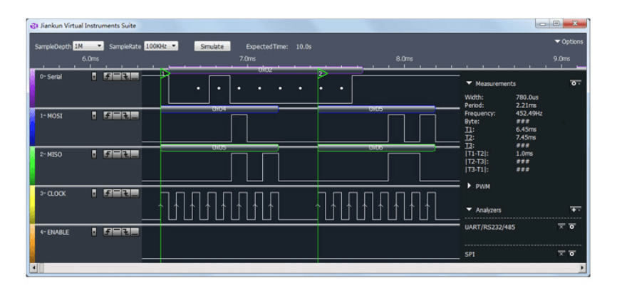
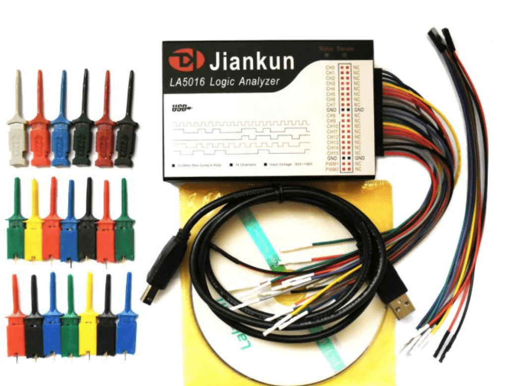
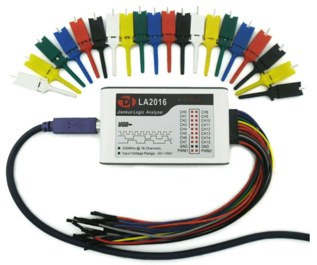
LA5016 is a high-performance logic analyzer with 16 channels and a 500M sampling rate. It is composed of two parts: software on personal computer and hardware equipment. It has the advantages of a high sampling rate, large sampling depth, easy to use, etc.
LA2016 can sample 16 digital signals at the same time. Then the sampled data can be displayed, analyzed, exported and saved on the computer. The software can also decode the data if it conforms to the standard protocol of the software supported. Then the decoded data can be displayed, exported and saved.
CAN Analyzers
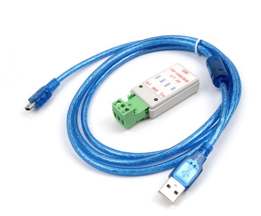
The USB-CAN Analyzer is a cost-effective high quality and easy to use USB to CAN adapter. You can just communicate your CAN-Bus device with your computer via the USB cable, then this tiny case will work as your CAN-Bus analyzer tool, CAN-Bus diagnostic tools, or CAN-Bus scanner.
We have released a wide variety of CAN-BUS devices, this USB-CAN Analyzer can be used with these devices. You can easily import the acquired CAN-BUS data to your computer for analysis.
Please also check Introduction to CAN-BUS and How to use it with Arduino to learn more about CAN-BUS
USB Cable and Charger Tester
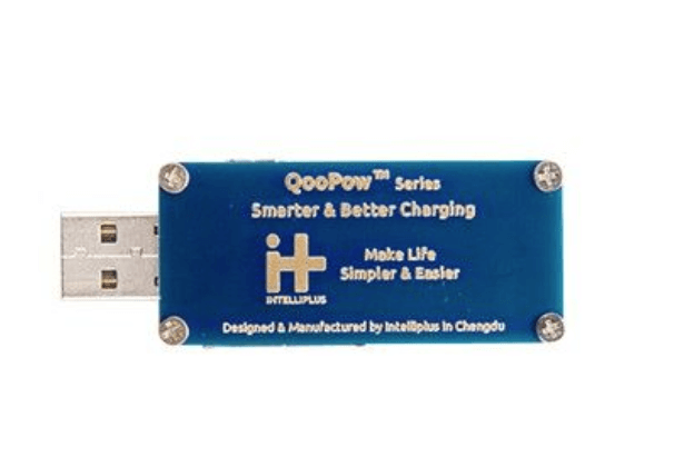
USB Cable and Charger Tester – qualMeter Basic can simply help you to diagnostic and get to know the quality of your USB cables and chargers in a glance without any technical background.
Simply connect both ends of your USB charging cable with qualMeter and plug it into any 5v USB charging port. You can read the LED indicators to have an idea about the quality of your charging cable.
qualMeter: Finally a Smart USB Cable/Charger Tester for Dummy
Spectrum Analyzers
A spectrum analyzer is an instrument that measures the magnitude of an input signal versus frequency within the full frequency range of the instrument. The primary use is to measure the power of the spectrum of known and unknown signals. The input signal that spectrum analyzers measure is electrical high frequency.
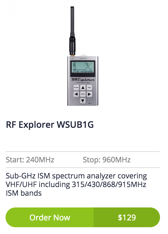
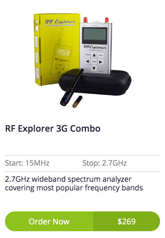
RF Explorer is a family of high-frequency tools designed to provide affordable instruments to assist in wireless projects. RF Explorer Spectrum Analyzers and Signal Generators provide unique capabilities including signal detection and hunting, interference and collision assistance, pre-compliance EMC testing and many other use cases.
RF Explorer WSUB1G features with wideband coverage to all popular sub-1Ghz ISM bands, including 315MHz, 433MHz, 868MHzand • 915MHz, also including UHF TV, 70cm and 33cm HAM radio, GSM, etc. Any frequency from 240MHz to 960MHz is covered.
RF Explorer 3G Combo includes a WSUB1G baseline unit plus an RFEMWSUB3G Expansion Module conveniently assembled and tested. It comes with two SMA connectors and two antennas: a nice Nagoya NA-773 wideband telescopic antenna for all Sub-GHz frequencies and a whip helical for 2.4GHz band. Additional, specific band antennas may be needed to cover efficiently some of the frequencies supported.
The combination of these two models offers coverage for most used communication frequency range used in modern communication technologies including WiFi, Bluetooth, Wireless Audio and Video, LTE, GSM, GPRS, Satellite, CATV, DTV, etc.
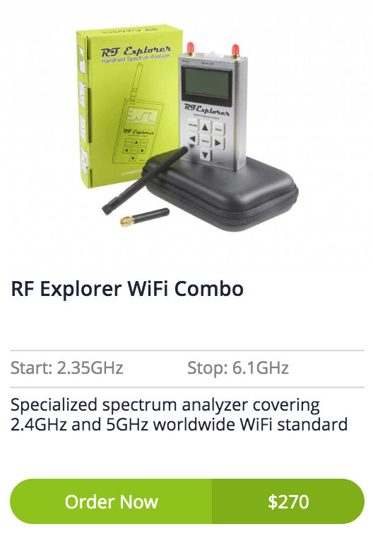
RF Explorer WiFi Combo is a handheld digital spectrum analyzer, a very affordable tool for work in all popular frequency bands. It is based on a highly integrated frequency synthesizer and double balanced mixer which offers high performance, compact size, low consumption, and low cost.
It has been designed to be used equally well outdoor and indoor and can be connected to a PC for extra functionality using standard mini-USB 2.0 connector.
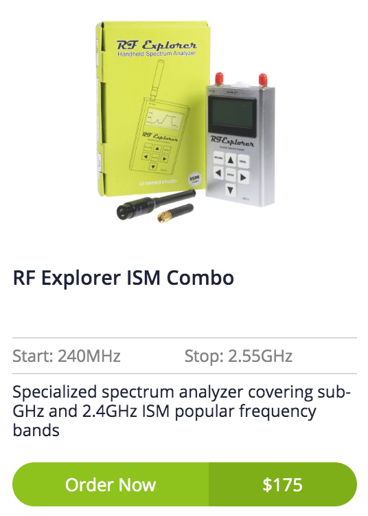
RF Explorer ISM Combo includes a WSUB1G baseline unit plus an RFEM2.4G Expansion Module conveniently assembled and tested. It comes with two SMA connectors and two antennas, a nice dual-band telescopic 144/430MHz wideband antenna for Sub-GHz frequencies and a whip helical for 2.4GHz band.
For more information for RF Explorer, please check: Introducing RF Explorer Spectrum Analyzer Product Family.
Antenna Analyzers
Antenna Analyzers devices aare used for measuring the input impedance of antenna systems. Antenna analyzers are widely used in the fields of antenna test development, installation, debugging, inspection and maintenance.
The SARK-110-ULM is the entry-level model of the SARK-110 antenna analyzer series, in the pocket-size. The built-in battery lasts up to eight hours on a single charge. It features a graphical display and an intuitive user interface that makes it easy to operate.
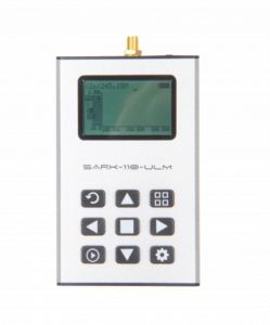
The native measurement frequency range is between 0.1 and 160 MHz, but it operates up to 700 MHz with reduced performances. It has full vector measurement capability and accurately resolves the resistive, capacitive and inductive components of a load.
You can use SARK-110-ULM for checking and tuning antennas, impedance matching, components test, cable fault location, measuring coaxial cable parameters and cutting coaxial cables to precise electrical lengths.
SPI Driver Adapter
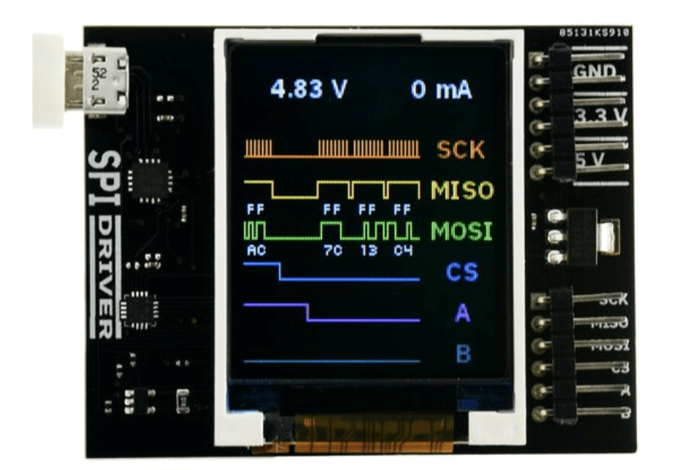
SPIDriver is an easy-to-use tool for controlling SPI devices. It works with Windows, Mac, and Linux, and has a built-in color screen that shows a live logic-analyzer display of all SPI traffic. It uses a standard FTDI USB serial chip to talk to the PC, so no special drivers need to be installed. The board includes 3.3 and 5 V supplies with voltage and current monitoring.
.gif)
To get started with the knowledge if SPI, UART, and Arduino basics, please check: Arduino Communication Peripherals: UART, I2C, and SPI
Power Supply
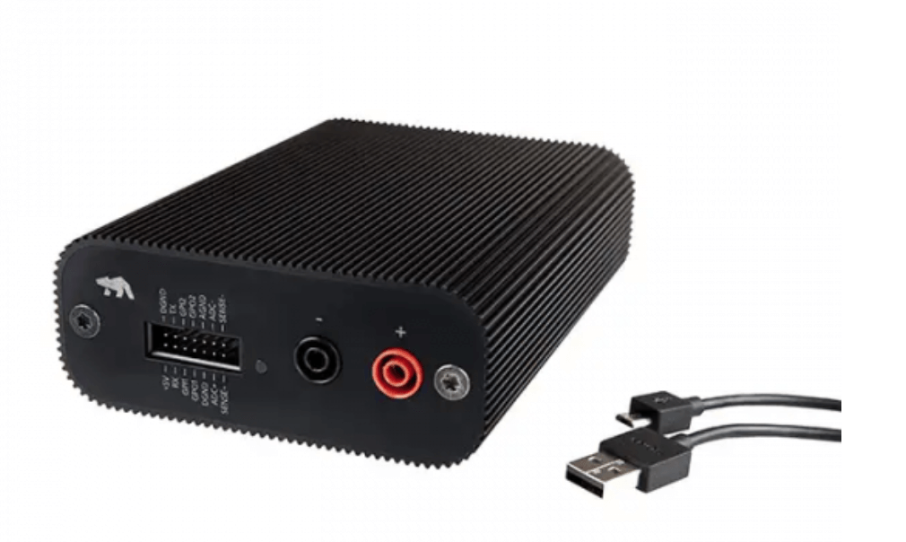
Otii Standard is the ultimate developer tool for anyone designing highly energy-efficient devices.
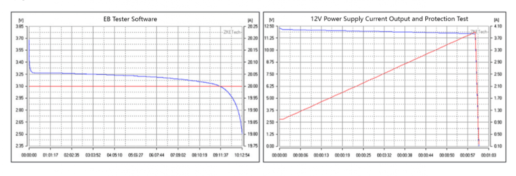
ZKETECH EBD-A20H DC Electronic Load/Battery Capacity & Discharge Tester/Power Supply Tester 30V 20A 200W
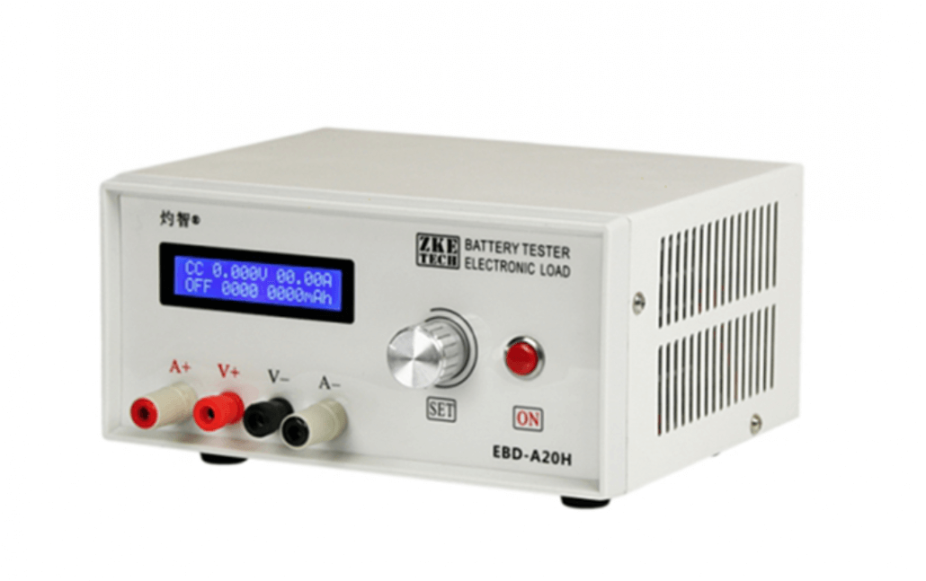
ZKETECH EBD-A20H is DC electronic load with multiple battery discharge modes and suitable for various battery capacity tests and power tests.
Special software called “EB software” is used along with this device in order to precisely display the relevant test information. The software supports features such as curve drawing, computer control and can perform calibration benchmark tests, automatic current testing and firmware upgrades.
Current Voltage Detector
With the help of the current and a voltage detector, you can determine the voltage or current precisely, which is essential for common measuring tasks.
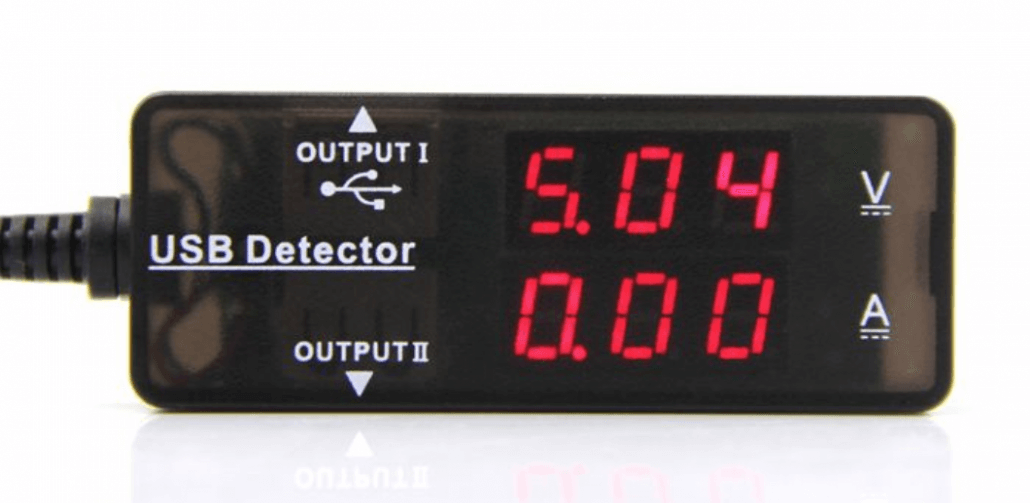
This USB Current Voltage Detector doesn’t need any external power , plug and play only. And it is not only voltage and current detect, but also a USB hub. As a common USB detecter, It has large detection range, 3.2v to 10v Voltage and 0A to 3A current.
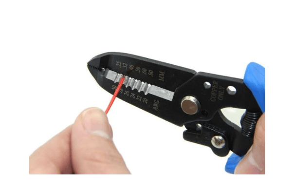
Hand Tools
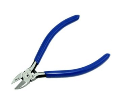
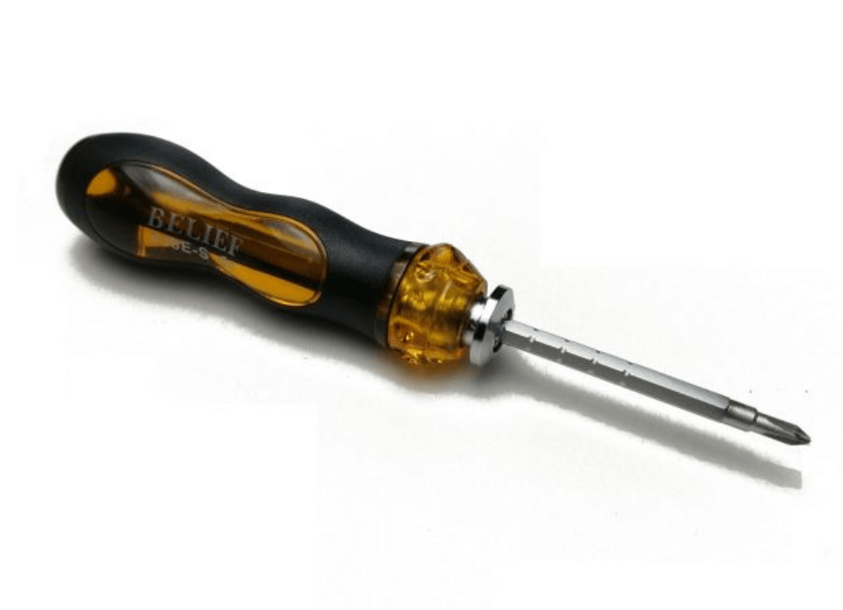
Every hacker will need basic hand tools to perform day to day tasks. At least you will need Wire Strippers ($4.90), pliers, tweezers, and Screwdrivers on your desk.
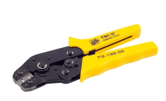
Soldering Tools
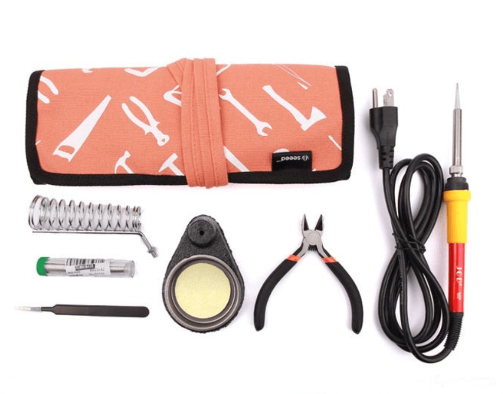
At Seeed, we offer individual components and also starter packs and kits with everything you need to build your own Soldering Station!
Soldering Individual Components
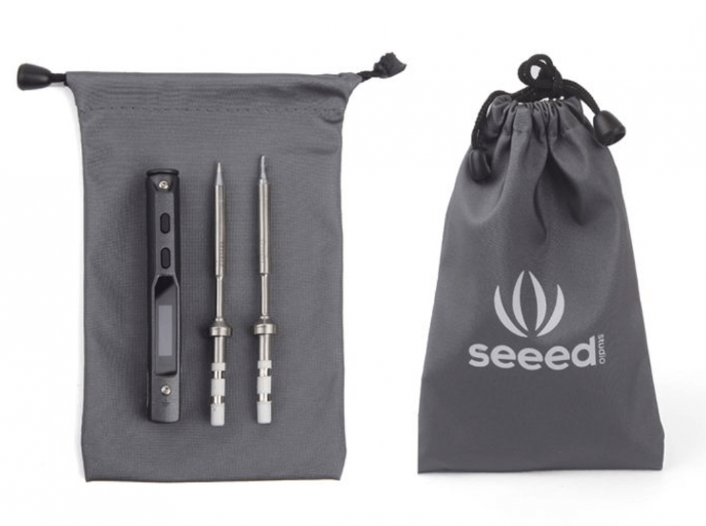
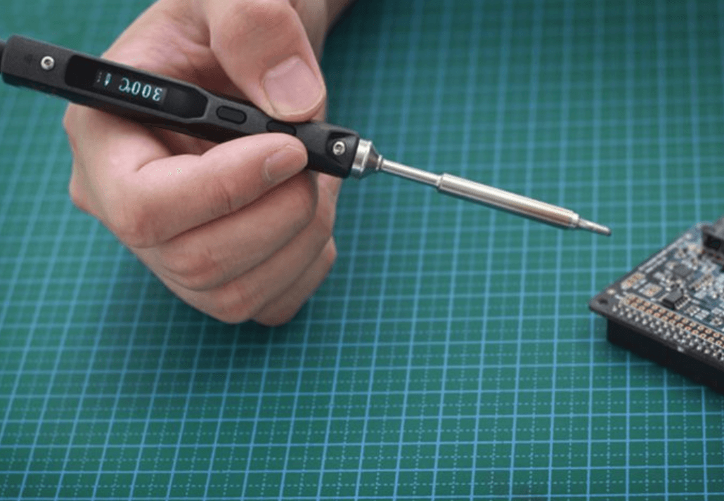
Mini Soldering Iron – US Standard (Shape-BC2) ($74.90)
- This Mini Soldering Iron is a small, lightweight, quick heating up soldering pencil which temperature can be accurately controlled from 100 °C to 400 °C with STM32
- It features dual temperature and accelerated sensors, sleep mode, and an automatic over-heating warning.
- Soldering iron tips are also replaceable with 4 different types and software can also be programmed.
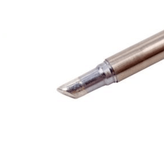
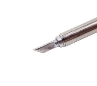
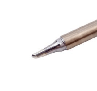
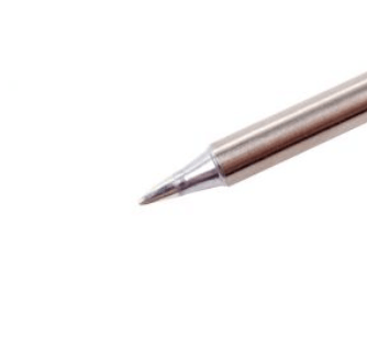
Soldering Irons

Soldering Irons Tip
Learn more about hand tools: Building your own Engineer Work Bench: Must have tools for every engineer!
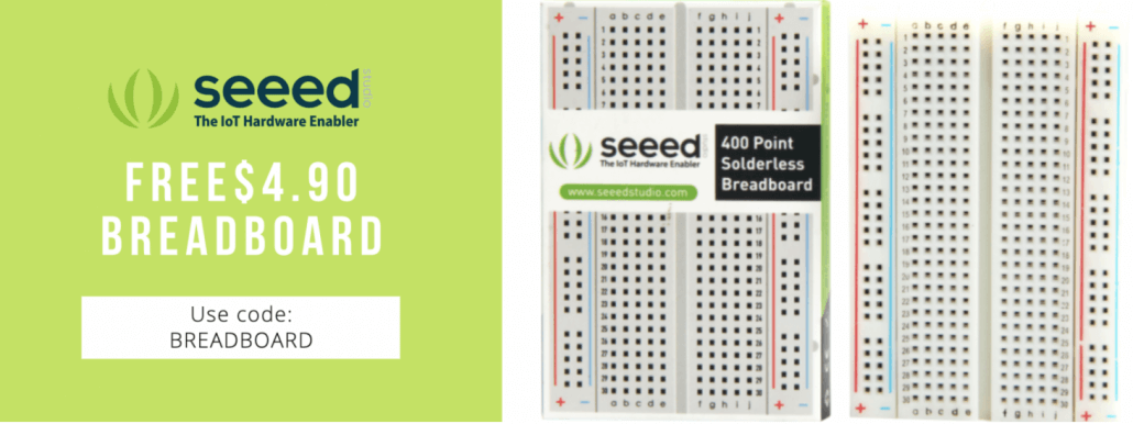
Breadboard
A breadboard is a solderless construction base used for developing an electronic circuit and wiring for projects with microcontroller boards like Arduino. As common as it seems, it may be daunting when first getting started with using one.
When you first lay your hands on a breadboard, you’ll find that there are many pinholes and start to wonder how do I start connecting things? However, before you get started, you’ll need to understand the components of a breadboard to avoid misusage.
1. Bus and Terminal Strips
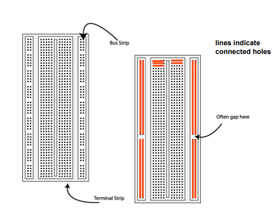
A breadboard consists of two areas called strips, and are often separated from the middle portion (commonly known as ravine).
- Bus strips are mainly used for power supply connections
- Terminal strips are mainly used for electrical components
- Each strip consist of 5 pinholes, indicating that you only can connect up to 5 components in one particular section
Note: Although each row has 10 pinholes, you can only connect 5 components as the ravine isolates both sides of a given row. This isolation restricts electrical connection between both sides.
2. How to wire a breadboard
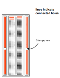
Note how the holes colored in orange are connected together. These sets of connecting holes can be called a node, where it’s possible to interconnect the node from bus strips to terminal strips with jumper wires!
Learn more about how to use breadboards: How to use a Breadboard for Beginners? Wiring, Circuit, Arduino
We will keep updating this topic so please stay tuned with us! Let us know what other tech tips you want to learn from our engineers and what tools you need for your workspace. We will carefully listen to and take action for communities!